Snowmobile Arctic Cat (2007 year). Manual - part 10


  Index      Snowmobiles / ATV     Snowmobile Arctic Cat - service manual 2007 year


Search            


Content   ..  8  9  10  11   ..


Snowmobile Arctic Cat (2007 year). Manual - part 10


2-25

2

AO182

29. Remove the hose clamp securing the main cool-

ant hose at the underside of the exhaust mani-

fold outlet; then remove the hose.

AO187

30. Remove the hose clamp securing the recircula-

tion hose to the main feed coolant hose; then

remove the hose.

AO187

31. Tilt the engine forward and support it suffi-

ciently to disconnect the fuel filter.

32. Using an appropriate hoist, remove the engine.

„ NOTE: Engine lift points consist of a bracket on
the front right side of the exhaust manifold and an
integral eye of the alternator adjustment bracket. 

Removing Engine

(1100 cc Z1)

1. Remove the hood and the right and left side

access panels.

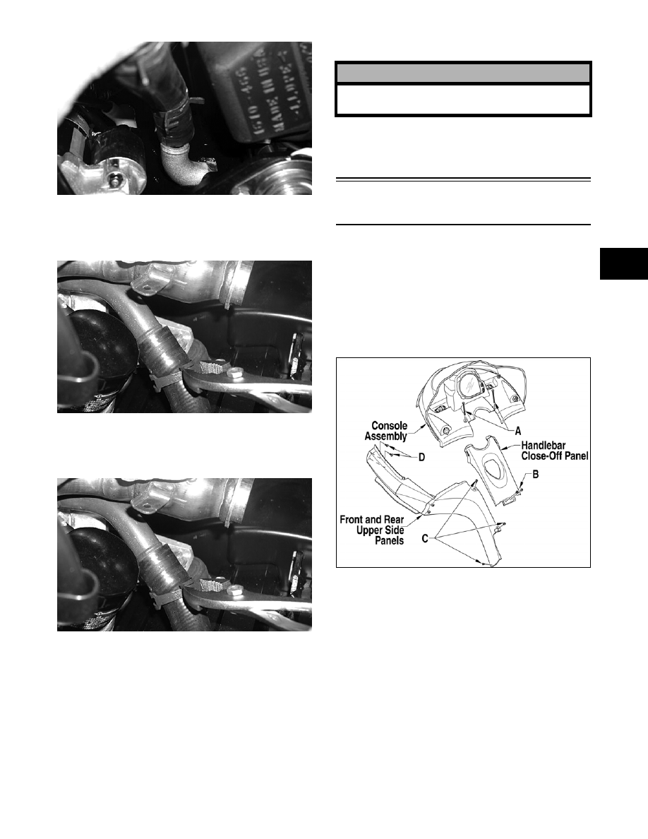
2. Remove the two torx-head cap screws (A)

securing the console to the chassis; then lift up

the rearward end of the console and disconnect

the console harness plug-in. Remove the con-

sole.

741-744A

3. Remove  the two screws securing the handlbar

close-off panel (B); then remove the three

screws (C) securing the front/rear upper side

panels to the seat support tubes. Remove the

screws (D) securing the front upper side panels

to the front bumper; then remove the side pan-

els.

4. Adjust the seat to the lowest position; then while

lifting on the top forward part of the seat,

remove the machine screw from the right side of

the seat support assembly. Remove the seat.

! CAUTION

Carefully observe that no hoses or wiring harnesses
are still connected to or caught on the engine.

2-26

ZJ100A

5. Disconnect the connector for the exhaust tem-

perature sensor; then remove the springs secur-

ing the exhaust pipe and resonator to the engine

and chassis. Remove the exhaust assembly and

account for exhaust gaskets and springs.

6. Remove the negative cable from the battery;

then remove the positive cable. Remove the

hardware securing the battery to the tray; then

remove the battery.

7. Remove the hose clamp from the coolant hose

(A) connecting the water pump to the right side

of the oil cooler; then clamp off the coolant hose.

With a drain pan positioned under the coolant

hose, remove the hose from the water pump;

then release the clamp. Tip the hose downward

allowing the coolant to drain completely.

ZJ101A

8. Using Drive Clutch Bolt Tool (p/n 0644-281),

remove the 12-mm Allen-head cap screw and

washer securing the drive clutch to the crank-

shaft. 

ZJ292

9. Using Clutch Puller (p/n 0644-446) and Drive

Clutch Spanner Wrench (p/n 0644-136), tighten

the puller until the drive clutch releases from the

crankshaft. Remove the drive clutch and drive

belt.

ZJ293

„ NOTE: If the drive clutch will not release, sharply
strike the head of the puller. Repeat this procedure
until the drive clutch releases. 

10. Using a 9/16-in. socket and extension, remove

the cap screw securing the driven pulley to the

input shaft.

ZJ250A

2-27

2

„ NOTE: After removing the driven pulley, account
for the cap screw and washers, sheave adjuster,
alignment washers, and O-ring from outside the
pulley; then from the input shaft, remove the two
1.5 mm (0.060 in.) washers along with any other
alignment washers. These washers must be used
during installing.

11. Remove the four cap screws (A) securing the

upper bearing bracket to the upper support plate;

then remove the four cap screws (B) securing

the support plate to the steering support.

ZJ097B

ZJ009B

12. Remove the six torx-head screws securing the

seat support assembly to the tunnel; then slide

the support back out of the way.

ZJ010A

13. Disconnect the fuel pump four-wire connector;

then slide the gas tank rearward enough to gain

access to the gasline hose connector.

ZJ011A

14. Compress the clip on the gasline hose connector

and remove the hose from the gas tank; then dis-

connect the gas tank vent hose and close off the

vent hose outlet of the gas tank.

ZJ012A

15. Remove the two torx-head cap screws securing

the air silencer to the chassis; then loosen the

screws on the clamps securing intake boot to the

throttle bodies.

ZJ013A

„ NOTE: Note the different-length cap screws for
installing purposes.

! CAUTION

The gasline supply hose may be under pressure.
Place an absorbent towel around the connection to
absorb gasoline; then remove the hose slowly to
release the pressure.

2-28

16. Remove the breather hose from the air silencer.

ZJ096B

17. Move the air silencer to the right until it

bypasses the bracket and move the air silencer

rearward; then disconnect the air temperature

sensor and remove the air silencer from the

chassis.

ZJ015A

18. Remove the two cap screws securing the head-

light support bracket to the right-side upper

frame; then remove the two cap screws and lock

nuts (A) securing the left-side upper frame to the

front end. Remove the one remaining cap screw

and lock nut (B) securing the upper frame to the

left-side skid plate.

ZJ025A

„ NOTE: For installing purposes, note the routing
path of the wiring harness and the location of the
cable ties securing the wiring harness to the left-
side upper frame; then remove the ties.

19. Remove the five cap screws and lock nuts secur-

ing the support gusset/left-side upper frame to

the steering support; then remove the MAP sen-

sor from the left-side upper frame and remove

the support bracket and left-side upper frame.

ZJ024A

20. Disconnect the harness plug-in (A) from the

chassis control unit; then remove the air pres-

sure sensor (B) from the bracket on the right-

side upper frame.

ZJ017A

21. Remove the hoses from the coolant tank and

thermostat; then remove the two coolant hoses

from the throttle bodies.

ZJ018A


Content   ..  8  9  10  11   ..