Snowmobile Arctic Cat (2007 year). Manual - part 2
1-5
1
NOTE: To ensure an accurate reading, the snow-
mobile should be on level ground.
2. If the oil level is at or below the ADD mark on
the oil level stick, add only enough recom-
mended oil to raise the level to the NORMAL
range. DO NOT overfill the reservoir with oil.
3. After adding oil if the engine starts, oil pressure
should be normal.
Check Engine Light
(660 cc/1100 cc Z1 Models)
The Check Engine Light is controlled by the ECU
and may illuminate for a number of reasons. The
light should illuminate each time the key is turned to
RUN or START, and it should go out when the
engine starts. If the light stays illuminated or it illu-
minates while the engine is running, the ECU is
receiving input that is outside of its established
parameters.
Diagnostic Codes/
Check Engine
(660 cc Models)
These diagnostic codes are flashed by the check
engine light incorporated within the speedometer/
tachometer (T660 models) or within the gauge hole
plate (Bearcat Wide Track/Panther 660 models).
Refer to the following chart for diagnostic code
sequences.
NOTE: On these double-digit codes (1-1, 1-3,
etc.), the first number indicated will flash in an
uninterrupted sequence, there will be a short
pause, and the second number indicated will flash
in an uninterrupted sequence.
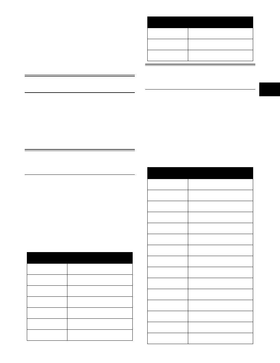
Diagnostic Codes/
Check Engine
(1100 cc Z1)
These diagnostic codes are flashed by the check
engine light incorporated within the speedometer/
tachometer. Refer to the following chart for diagnos-
tic code sequences.
NOTE: On single-digit codes (2, 3, etc.), the num-
ber indicated will flash in an uninterrupted
sequence. On double-digit codes (1-1, 1-2, etc.),
the first number indicated will flash in an uninter-
rupted sequence, there will be a short pause, and
the second number indicated will flash in an unin-
terrupted sequence.
Number of Flashes
Trouble
1-1
(Check Engine Light)
Open or short circuit in manifold air
pressure sensor.
1-3
(Check Engine Light)
Open or short circuit in
throttle position sensor.
1-4
(Check Engine Light)
Failure in oxygen sensor.
1-5
(Check Engine Light)
Failure in crankshaft position sensor.
1-6
(Check Engine Light)
Failure in speed sensor.
1-7
(Check Engine Light)
Open or short circuit in
knock sensor.
1-8
(Check Engine Light)
Open or short circuit in intake
manifold air temperature sensor.
1-9
(Check Engine Light)
Open or short circuit in
water temperature sensor.
2-7
(Check Engine Light)
Failure in coil.
2-9
(Check Engine Light)
Failure in barometric
pressure sensor.
Number of Flashes
Trouble
1
(Check Engine Light)
Failure in the fuel system.
1-1
(Check Engine Light)
Failure in speed sensor.
1-2
(Check Engine Light)
Failure in coil (#1).
1-3
(Check Engine Light)
Failure in coil (#2).
1-4
(Check Engine Light)
Failure in ISC valve.
1-5
(Check Engine Light)
Failure in oxygen sensor.
1-9
(Check Engine Light)
Failure in camshaft position sensor.
2
(Check Engine Light)
Failure in injector (#2).
3
(Check Engine Light)
Failure in injector (#1).
4
(Check Engine Light)
Failure in barometric pressure sen-
sor.
5
(Check Engine Light)
Open or short circuit in intake mani-
fold air temperature sensor.
6
(Check Engine Light)
Open or short circuit in water tem-
perature sensor.
7
(Check Engine Light)
Open or short circuit in throttle posi-
tion sensor.
8
(Check Engine Light)
Open or short circuit in manifold air
pressure sensor.
9
(Check Engine Light)
Failure in crankshaft position sensor.
Number of Flashes
Trouble