Snowmobile Arctic Cat (2004 year). Manual - part 160
9-156
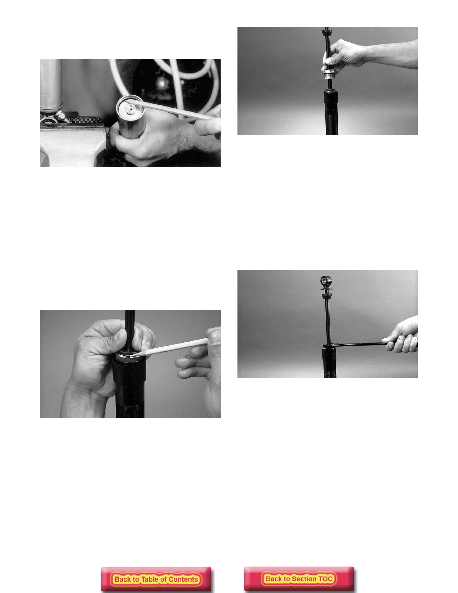
6. Install the reservoir end cap and O-ring down into
the reservoir approximately 2.5 cm (1 in.). Install
the retainer ring making sure it is firmly in place.
AP011
7. Grasp the bladder housing with a pliers and pull it
up into place against the retainer ring.
8. Slowly pour oil into the shock body until it is 1/4
in. from the top of the shock body. Again, allow
five minutes to elapse before proceeding.
9. Space the bottom edge of the bearing cap approxi-
mately 1/2 to 1 in. away from the piston assembly.
10. To install the shock rod, align the valve piston
wear ring end gap with the low-speed orifice cut-
away positioning the cutaway so it faces the
upward angle of the shock body which will allow
air to escape.
AG860
11. Compress the piston ring into position with fingers
and slowly start the piston assembly down into the
shock body.
AG853
12. Give the end of the shock rod a few light taps with
the palm of the hand to help release air bubbles
from the piston valves.
NOTE: Be careful not to damage the piston ring
and watch that the piston ring ends are overlapped
and in place as the piston is installed.
13. Install the end cap very slowly to allow excess air
and oil to come out the threads; then using a 1-in.
wrench, tighten the bearing cap firmly down in
place. Do not push down on the shock shaft until
the reservoir has been pressurized. Pressurize the
reservoir.
AG852
14. Discharge all pressure from the shock reservoir
using Shock Inflation Needle (p/n 0644-158).
Open valve in filler handle until all pressure is
released.
15. Push down on the reservoir end cap compressing it
2.5 cm (1 in.) into the reservoir; then remove the
reservoir cap retainer ring. Use care not to scratch
the inside of the reservoir.
16. Measure the piston depth from the top of the reser-
voir body to the top of the floating piston. Mea-
surement should be within specification (see
Rebuildable Shock Piston Depth Chart in this sec-
tion). If measurement is not correct, pour 1 inch of
shock oil on top of the piston. Remove the Allen-
head screw; then move the piston to the proper
depth and install Allen-head screw with O-ring.