Snowmobile Arctic Cat (2004 year). Manual - part 95


  Index      Snowmobiles / ATV     Snowmobile Arctic Cat - service manual 2004 year


Search            


Content   ..  93  94  95  96   ..


Snowmobile Arctic Cat (2004 year). Manual - part 95


7-44

FC225

„

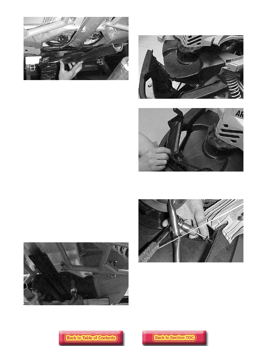
NOTE: If removing the right-side belly pan only,

the resonator must be removed. If removing the
left-side belly pan only, the clutch guard must be
removed.

6. Remove the 10 torx-head screws securing each

side belly pan to the frame.

7. Using a 3/16 in. drill bit, drill out the six rivets

securing each side belly pan to the frame; then
remove the belly pans.

INSPECTING

1.  Inspect for gouges, cuts, and tears.

2.  Inspect all belly pan threaded bosses that they are

in good shape. 

INSTALLING

„

NOTE: Steps 1-2 should be used for each side

belly pan.

1. Place the side belly pan into position on the frame;

then secure with the 10 torx-head screws.

2. Using an appropriate rivet gun, secure the side

belly pan with six rivets.

3. Place the rear belly pan into position; then secure

with the 10 torx-head screws.

FC224

4. Place the front bumper into position; then secure

with the eight torx-head screws. Place the center
belly pan screen into position.

FC221

FC222

5. Place the air silencer into position on the front

bumper; then secure with the three torx-head
screws. 

FC217

6. Place the hood into position on the front bumper;

then install the two hood pins and hairpin clips.

7-45

7

FC219

„

NOTE: If applicable, install the resonator and/or

the clutch guard.

Gas Tank/Seat 

Assembly

(AWS V)

„

NOTE: Some components may vary from model

to model. The technician should use discretion
and sound judgment.

REMOVING

„

NOTE: If so equipped, turn the gas tank shut-off

valve to the CLOSED position. 

1. Remove the console (see the appropriate Console

in this section).

2. Remove the two cap screws, washers, and lock

nuts (located in the rear compartment) securing the
seat to the tunnel.

3.  Remove the vent hose from the gas tank.

4. On EFI models, disconnect the wiring harness

from the fuel pump. Label the fuel hoses “supply”
and “return”; then remove the hoses from the fuel
pump.

5. Raise the rear of the seat high enough to discon-

nect the taillight wiring harness.

6. On the carbureted models, slide the gas tank/seat

assembly back far enough to access the fuel hose;
then disconnect the fuel hose. 

7.  Remove the gas tank/seat assembly.

INSTALLING

1. Place the seat in position on the tunnel; then on

carbureted models, connect the fuel hose. 

2.  Connect the vent hose to the gas tank.

3.  On EFI models, connect the fuel supply and return

hoses to the fuel pump. Secure with clamps; then
connect the wiring harness to the fuel pump.

4. Raise the rear of the seat high enough to connect

the taillight wiring harness making sure the
harness is positioned into the groove of the seat
base. 

„

NOTE: On EFI models, the fuel hoses must be

connected to their respective fittings and tight-
ened securely or leakage will result.

5.  Secure the seat to the tunnel with two cap screws,

washers, and lock nuts.

6.  Install the console (see the appropriate Console in

this section).

Gas Tank/Seat 

Assembly

(AWS VI)

REMOVING

1. On Firecat models from inside the rear compart-

ment, remove the nut and washer securing the
assembly to the tunnel; then remove the seat
assembly.

FC228

2.  On Sabercat models, unhook the hold-down straps

and remove the storage compartment; then trip the
seat latches and remove the seat.

3. Remove the console (see the appropriate Console

in this section).

4.  Drain the gasoline from the gas tank.

! CAUTION

Since the fuel supply hose may be under
pressure, remove it slowly to release the
pressure. Place an absorbent towel around the
connection to absorb fuel.

7-46

5. Remove the two lock nuts and two torx-head cap

screws with nuts securing the steering post
mounting block. Account for the plastic steering
post mounting block and the retaining plate.

FC203

6.  Remove the nine lock nuts securing the gas tank to

the tunnel and footrests; then remove the four torx-
head screws securing the side belly pans to the
tank. Account for all mounting hardware.

FC229

FC230

7. Remove the fuel hose from the lower right-side

corner of the tank; then remove the gas tank
assembly. 

FC231

INSTALLING

1.  Install the fuel hose to the lower right-side corner

of the gas tank; then place the gas tank assembly
into position on the tunnel. 

FC231

2. Secure the side belly pans to the tank with the four

torx-head screws; then secure the tank to the
footrests and tunnel with the nine lock nuts.

FC230

7-47

7

FC229

3. Place the steering post mounting block and

retaining plate into position taking care not to
pinch any wiring and making sure the brakeline
hose is positioned behind the retaining plate. 

FC203

FC204

4. Tighten the nuts to 1.4 kg-m (10 ft-lb).

5.  Install the console (see the appropriate Console in

this section).

6. On Firecat models from inside the rear compart-

ment, secure the seat assembly to the tunnel with
the nut and washer. 

FC228

7. On Sabercat models, place the seat into position

and secure with the latches; then install the storage
compartment.

Seat Cushion

„

NOTE: Some components may vary from model

to model. The technician should use discretion
and sound judgment. 

REMOVING

„

NOTE: Steps 1-3 do not apply to Sabercat mod-

els.

1.  Remove the gas tank/seat assembly (see the appro-

priate Gas Tank/Seat Assembly in this section).

2. Remove the two screws securing the taillight

cover; then remove the cover. 

3. Remove the two screws securing the front of the

seat cushion to the seat base. 

4.  On Sabercat models, remove the three self tapping

screws securing the seat panel to the back of the
seat assembly.

5.  Using a sharp tool, pry out all staples securing the

seat cover to the plastic seat base.

6.  From beneath the seat foam, remove the seat wire

from the two elastic loops; then remove the cover
from the seat base and seat foam.

INSTALLING

„

NOTE: If the seat cover was removed, position

the cover over the seat foam and plastic seat base.
Check to make sure it is positioned straight; then
fold the rear edge of the cushion down and around
the base. Using a staple gun and 6 mm (1/4 in.) sta-
ples, staple the rear flap of the cushion to the base
in the same areas as the original staples were
located. Position staples 2.5 cm (1 in.) apart. Fold
the sides of the cushion down around the bottom
edge of the base. Position the staples in the same
areas as the original staples were located.


Content   ..  93  94  95  96   ..