Snowmobile Arctic Cat (2004 year). Manual - part 23


  Index      Snowmobiles / ATV     Snowmobile Arctic Cat - service manual 2004 year


Search            


Content   ..  21  22  23  24   ..


Snowmobile Arctic Cat (2004 year). Manual - part 23


2-79

2

AN118

„

NOTE: Before installing the flywheel, be sure to

wipe the crankshaft and flywheel tapers clean
using a clean towel.

43. Install the key in the crankshaft and slide the

flywheel onto the crankshaft making sure the
keyways match; then finger-tighten the flywheel
nut with large flat washer and lock washer. Apply
red Loctite #271 to the threads of the flywheel nut.

44. Install the starter pulley; then secure the starter

pulley with three cap screws and lock washers.
Secure the pulley while using the spanner wrench
and tighten the three cap screws evenly to 0.7-
1 kg-m (5-7 ft-lb).

AN121

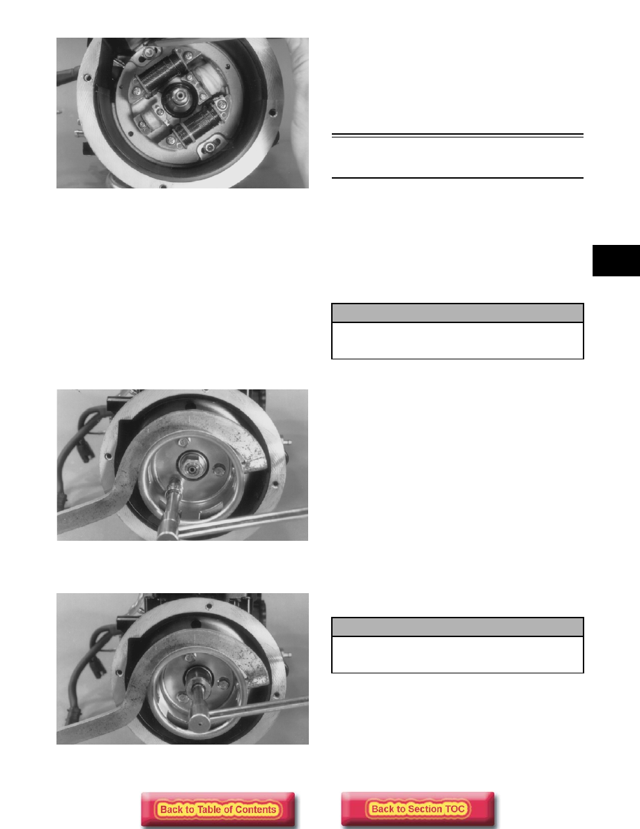
45. Using the spanner wrench, tighten the flywheel

nut to 7-9 kg-m (50.5-65 ft-lb).

AN122

46. Install the spark plugs and tighten to 2.5-2.8 kg-m

(18-20 ft-lb). Connect the spark plug caps.

47. Place the engine mounting brackets into position

on the crankcase and secure with the cap screws.
Tighten to 2.8-3.5 kg-m (20-25 ft-lb).

Assembling Engine

(570 cc Models)

„

NOTE: The use of new gaskets and seals is rec-

ommended when assembling the engine.

„

NOTE: When the use of a lubricant is indicated,

use Arctic Cat 50:1 Injection Oil.

 1. Place the upper crankcase half (with its bottom

side up) on two blocks of wood.

2. Lightly grease the inner lips of the crankshaft

seals; then slide them onto the crankshaft.

3. Apply oil to the crankshaft bearings; then install

the crankshaft into the upper crankcase half. Be
sure the alignment hole in each bearing is
positioned over its respective dowel pin in the
crankcase; then seat the crankshaft.

„

NOTE: To check the bearing for proper position,

place the point of a sharp tool into the dimple
found in the bearing race. Strike the tool with the
palm of the hand in either direction. If the bearing
moves, it isn’t positioned correctly and must be
rotated until it drops onto the dowel pin. 

„

NOTE: Make sure the crankshaft center C-ring

(integral with the center seal) is properly posi-
tioned in the groove of the upper crankcase half.

4. Install the four crankcase dowel pins.

5. Evenly apply a thin coat of Three Bond Sealant (p/n

0636-070) to the entire bottom half crankcase
sealing surface. 

„

NOTE: Use only Three Bond Sealant (p/n 0636-

070) to seal the crankcase halves.

! CAUTION

To prevent damage to the crankshaft, crankshaft
bearings, or seals, make sure to always lift the
crankshaft from both ends.

! CAUTION

If the bearings are not properly seated during
assembly, the crankcase halves will not seal
tightly and severe engine damage will result.

2-80

MD0203

6. Install crankcase lower half. Install eight 8 mm

and four 6 mm cap screws. Tighten in three steps
the 8 mm cap screws to 1.8-2.8 kg-m (13-20 ft-lb)
and the 6 mm cap screws to 0.8-1.2 kg-m (6-9 ft-
lb) using the pattern shown.

737-027A

MD0212

„

NOTE: Check the reed valve on each cylinder for

cracking or fraying around the edges. Make sure
they are closing completely.

„

NOTE: To inspect a reed valve assembly, remove

the two Phillips-head screws securing the reed
valve and reed valve stopper to the block; then
remove the reed valve and stopper.

MD0088

„

NOTE: Apply blue Loctite #242 on the Phillips-

head screws when assembling.

„

NOTE: Make sure the angled corner on the reed

valve align with the angled corner on the reed
valve stopper.

MD0213

  7.  Install the piston rings on each piston so the letter

on the top (inclined surface) of each ring faces the
dome of the piston.

! CAUTION

Do not over-tighten the Phillips-head screws
when installing the reed valves and reed valve
stoppers.

2-81

2

726-306A

„

NOTE: If the existing rings will not be replaced

with new rings, note the location and top side of
each ring for proper installation. When replacing
with new rings, replace as a complete set only.
When replacing rings note notches in ring ends
which correspond with locating pins in ring
grooves on intake side of the piston. This prevents
the rings from turning on the piston when assem-
bled.

MD0208

MD0272

MD0271

8. Lubricate the piston pin bearings and install them

into the connecting rods. 

9.  Install a piston pin bearing washer on each side of

the bearings with the open sides facing the
bearings.

„

NOTE: The open sides of the piston pin bearing

washers must face the bearing.

MD0251

10. Place pistons over the connecting rods with the

arrow (or indicator dot) pointing toward the
exhaust port; then secure with an oiled piston pin.
Install piston pin circlips with the open ends up or
down.

MD0293

! CAUTION

Incorrect installation of the piston rings will
result in engine damage.

2-82

MD0248

11. Place the cylinder base gasket into position on the

crankcase making sure the gasket is properly
oriented so the dowel pins will fit through the
holes easily.

„

NOTE: Be sure to spray a thin coat of Copper

Coat Gasket Sealant (p/n 0636-092) onto the gas-
ket if it is being reused.

12. Rotate each piston ring until the ring ends are

properly positioned with the pins in the ring
grooves; then apply oil to the piston assemblies
and cylinder bores. Using a ring compressor or the
fingers, compress the rings and slide the cylinder
over the piston. Seat the cylinder firmly onto the
crankcase. 

„

NOTE: The cylinders should slide on easily. DO

NOT force them on.

MD0229

13. Secure each cylinder by installing the four 6 mm

and eight 8 mm nuts. Tighten the 8 mm nuts to 4-6
kg-m (29-43.5 ft-lb) and the 6 mm nuts to 0.7-1
kg-m (5-7 ft-lb).

MD0086

MD0087

14. Install a new cylinder head gasket and the cylinder

head; then install the eight cap screws and two
nuts with washers. Tighten in three steps to 1.8-2.8
kg-m (13-20 ft-lb) using the pattern shown. 

MD0232

! CAUTION

Make sure the circlips are firmly seated in their
grooves and the open ends are pointed up or
down before continuing with assembly.


Content   ..  21  22  23  24   ..