Snowmobile Arctic Cat (2004 year). Manual - part 12


  Index      Snowmobiles / ATV     Snowmobile Arctic Cat - service manual 2004 year


Search            


Content   ..  10  11  12  13   ..


Snowmobile Arctic Cat (2004 year). Manual - part 12


2-35

2

18. Using a rubber hammer, gently tap the cylinders

and remove from the crankcase by lifting them
straight up off their studs. Discard the two gaskets.
Account for two dowel pins.

19. Using a felt-tipped marker, mark an M on the

MAG-side head, cylinder, and piston and a P on
the PTO-side head, cylinder, and piston.

„

NOTE: For proper assembly, keep all MAG-side

components and all PTO-side components sepa-
rated. Assemble them on their proper sides.

20. Remove the PTO-side piston-pin circlip from the

PTO-side piston; remove the MAG-side piston-pin
circlip from the MAG-side piston.

A829

21. Using the Piston-Pin Puller (p/n 0644-328),

remove the piston pins from both pistons.

A830

22. Lift the pistons clear of the connecting rods and

remove the small end connecting-rod bearings;
then remove the piston rings. Keep each piston
with its rings, piston pin, and bearing together as a
set.

„

NOTE: Place rubber bands over the connecting

rods and around the cylinder studs. This will keep
the connecting rods from damaging the crank-
case.

B160

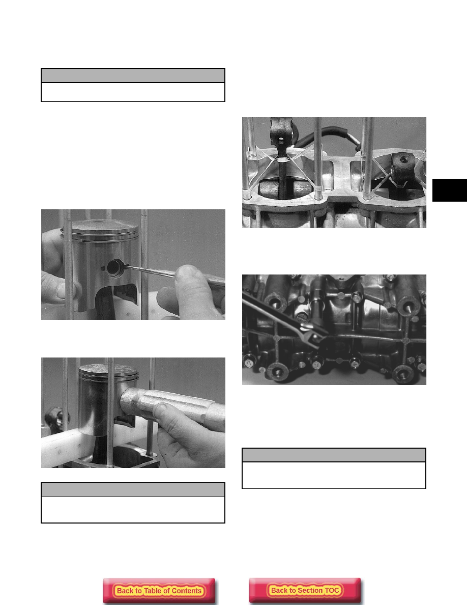
23. Remove the cap screws securing the crankcase

halves. Note the position of the different-sized cap
screws.

A831

24. Separate the crankcase halves by installing two

crankcase cap screws in diagonal corners leaving
the heads approximately 6 mm (1/4 in.) out. Using
a plastic hammer, tap on each cap screw head until
the halves separate. Remove the cap screws.

25. Remove the rubber bands holding the connecting

rods; then separate the crankcase halves. Account
for the two dowel pins. Lift the crankshaft free
from the crankcase half and slide the two
crankshaft seals off the crankshaft. Account for the
C-ring and five bearing retaining pins.

! CAUTION

When removing a cylinder, make sure to support
the pistons so they will not be damaged.

! CAUTION

DO NOT use any type of punch to drive the
piston pin free of the piston; damage may result.
Use a piston-pin puller only.

! CAUTION

DO NOT drive any tool between the crankcase
halves to separate the crankcase. Damage to the
sealing surfaces will result.

2-36

Disassembling Engine

(550 cc Model)

1. Using the spanner wrench to secure the flywheel,

remove the flywheel nut, lock washer, and flat
washer; then remove the three starter pulley cap
screws and remove the pulley.

AN015

2. Install the Crankshaft Protector Cap (p/n 0644-

234) onto the end of the crankshaft.

„

NOTE: A suitable substitute protective cap can

be made by welding a 3 mm (1/8 in.) plate on one
side of a spare flywheel nut.

3. Using the Flywheel Puller/Spanner Wrench (p/n

0144-310) or suitable substitute, remove the
flywheel from the crankshaft by tightening the
puller bolt, striking the head of the puller bolt with
a hammer, and tightening again. Repeat this
procedure until the flywheel is free. Account for
the key.

AN020

„

NOTE: To ensure the cleanliness of the flywheel

magnets, place the flywheel (with the magnets fac-
ing upward) on a clean bench.

4. Scribe a line on the stator plate and magneto case

to aid in assembly; then remove the two Allen-
head cap screws, lock washers, and washers
securing the stator plate. Remove the stator plate
from the engine.

AN022

„

NOTE: The stator plate screws had Loctite

applied to the threads during assembly. Using an
impact driver, apply a sharp blow to the head of
each screw to break the Loctite loose before
removal.

5. Remove the four nuts and lock washers securing

the exhaust manifold.

6. Remove the manifold and account for the two

exhaust gaskets.

7. Remove the three cap screws securing the

thermostat cap; then remove the cap, gasket, and
thermostat.

„

NOTE: The thermostat is of the lock-open type. If

the thermostat is ever allowed to fully open, it will
remain open and replacement will be necessary.

8. Remove the four cap screws securing the

thermostat manifold to the cylinder heads.
Remove the manifold and discard the gaskets.

9. Remove the spark plugs.

10. Remove the six cap screws and O-rings securing

each head; then separate from the cylinder.
Account for two large O-rings beneath each head.

11. Remove the oil-injection hose from each cylinder

and the crankcase nozzle.

! CAUTION

To prevent damage to the crankshaft, the puller
must bottom on the cap and not on the
crankshaft. Also, do not thread puller bolts more
than 12.7 mm (1/2 in.) into the flywheel. Damage
to the coils may result.

2-37

2

AN032

12. Remove the eight nuts, lock washers, and washers

securing the cylinders to the crankcase; then using
a rubber hammer, gently tap the cylinders and
remove from the crankcase by lifting them straight
up off their studs. Account for two gaskets.

„

NOTE: The metal cylinder base gaskets may be

reused. When reusing gaskets, they must be
cleaned and sprayed with Copper Coat Gasket
Sealant (p/n 0636-092) on each side.

AN033

„

NOTE: If servicing the intake flanges, remove

them at this time.

13. Remove the PTO-side piston-pin circlip from the

PTO-side piston; then remove the MAG-side
piston-pin circlip from the MAG-side piston.

14. Using the Piston Pin Puller (p/n 0644-328),

remove the piston pins from both pistons.

„

NOTE: For proper assembly, keep all MAG-side

components and all PTO-side components sepa-
rated. Assemble them on their proper sides.

AN036

15. Lift the pistons clear of the connecting rods and

remove the small-end connecting-rod bearings;
then remove the piston rings. Keep each piston
with its rings; keep each piston pin and bearing
together as a set.

„

NOTE: Place rubber bands over the connecting

rods and around the cylinder studs. This will pre-
vent the connecting rods from damaging the
crankcase.

16. Remove the two screws, lock washers, and

washers securing the oil-injection pump to the
crankcase. Remove the pump, retainer, and O-ring.

17. Remove the water pump cover. Account for the O-

ring gasket.

18. Remove the cap screw securing the water pump

impeller; then slide the impeller free of the shaft.

19. Using an impact driver, remove the screws

securing the PTO-end plate to the crankcase; then
remove the plate.

20. Position the crankcase (with its bottom side up) on

two blocks of wood. Remove the fourteen cap
screws securing the crankcase halves. Note the
position of the different-sized cap screws.

21. Separate the crankcase halves by installing two

crankcase cap screws in opposite corners leaving
the heads approximately 6 mm (1/4 in.) out. Using
a plastic-tipped hammer, tap on each cap screw
head until the case halves separate. Remove the
cap screws.

! CAUTION

When removing a cylinder, be sure to support
the piston to prevent damage to the crankcase
and piston.

! CAUTION

DO NOT use any type of punch to drive the
piston pin free of the piston; damage may result.
Use a piston-pin puller only.

! CAUTION

DO NOT drive any tool between halves to
separate the crankcase. Damage to the sealing
surfaces will result.

2-38

AN045

22. Lift the bottom half of the crankcase off the top

half.

23. Lift the crankshaft free from the top half of the

crankcase and slide the crankshaft oil seals off the
crankshaft. Account for the C-ring. Remove the
two dowel pins and the four bearing retaining pins.

24. Remove the oil-injection pump driveshaft from the

lower crankcase half. Account for the thrust
washer on the outer end of the shaft.

AN047

„

NOTE: Do not replace the inner seals unless the

water pump shows signs of leaking coolant out of
the small bleed hole in the bottom half of the
crankcase. If a water pump seal is to be replaced,
use the Water Pump Bearing and Seal Kit (p/n
0644-084) and see Cleaning and Inspecting Engine
in this section.

25. Place the crankcase on the bench with the water

pump side down. Using the long seal driver, drive
the water pump seal from the crankcase.

AN049

26. Remove the snap ring securing the inner seal in the

crankcase.

27. Using the hooked end of the tool, pull the inner

seal free of the crankcase.

AN050

28. Using a sharp, pointed tool, pry the seal ring from

the backside of the water pump impeller.

AN051


Content   ..  10  11  12  13   ..