Snowmobile Yamaha Phazer PZ50W, PZ50GTW, PZ50FXW, PZ50MW, PZ50VTW, PZ50MPW. Manual - part 57
5-65
ENG
5. Measure:
• Piston ring end gap
Out of specification
→ Replace the piston
rings as a set.
NOTE:
The oil ring expander spacer’s end gap cannot be
measured. If the oil ring rail’s gap is excessive,
replace all three piston rings.
6. Inspect:
• Piston pin
Blue discoloration/grooves
→ Replace the
piston pin and then check the lubrication sys-
tem.
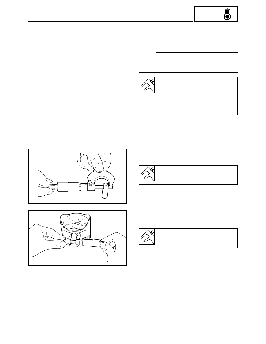
7. Measure:
• Piston pin outside diameter
Out of specification
→ Replace the piston pin.
Piston ring end gap:
Top ring:
0.15 ~ 0.25 mm (0.006 ~ 0.010 in)
2nd ring:
0.30 ~ 0.45 mm (0.012 ~ 0.018 in)
Oil ring:
0.10 ~ 0.40 mm (0.004 ~ 0.016 in)
Piston pin outside diameter:
16.991 ~ 17.000 mm
(0.6689 ~ 0.6693 in)
8. Measure:
• Piston pin bore inside diameter
Out of specification
→ Replace the piston.
Piston pin bore inside diameter:
17.002 ~ 17.013 mm
(0.6694 ~ 0.6698 in)