Snowmobile Yamaha Phazer PZ50W, PZ50GTW, PZ50FXW, PZ50MW, PZ50VTW, PZ50MPW. Manual - part 26
3-23
CHAS
INSTALLATION
1. Install:
• Stabilizer 1
• Bushing 2
• Stabilizer holder 3
CAUTION:
Always install the stabilizers, bushings, and
stabilizer holders in the same positions on both
sides of the snowmobile, otherwise poor han-
dling and loss of stability may result. (PZ50GT/
PZ50VT/PZ50MP)
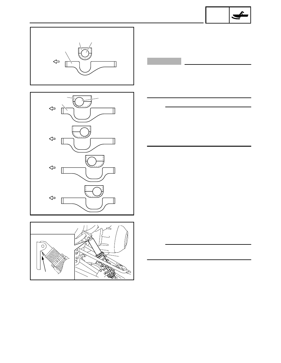
NOTE:
• Install the stabilizer holder in the direction shown
in the illustration. (PZ50/PZ50FX/PZ50M)
• The stabilizer force can be adjusted by changing
the installation positions of the stabilizer, bushing,
and stabilizer holder. (PZ50GT/PZ50VT/
PZ50MP)
È PZ50/PZ50FX/PZ50M
É PZ50GT/PZ50VT/PZ50MP
a Forward
b Very hard
c Hard
d Medium
e Soft
Stabilizer, bushing, and stabilizer holder stan-
dard installation positions:
d (PZ50GT)
b (PZ50VT/PZ50MP)
a
1
2
3
È
b
c
d
e
a
a
a
a
1
2
3
É
2. Install:
• Shock absorber 1 (PZ50GT/PZ50VT
“Europe”/PZ50MP)
NOTE:
Install the shock absorber with the charging valve
a facing inward.
a
1