Snowmobile Yamaha Phazer PZ50W, PZ50GTW, PZ50FXW, PZ50MW, PZ50VTW, PZ50MPW. Manual - part 1


  Index      Snowmobiles / ATV     Snowmobile Yamaha Phazer PZ50W, PZ50GTW, PZ50FXW, PZ50MW, PZ50VTW, PZ50MPW - service manual 2007 year


Search                


Content   ..  1  2  3   ..


Snowmobile Yamaha Phazer PZ50W, PZ50GTW, PZ50FXW, PZ50MW, PZ50VTW, PZ50MPW. Manual - part 1


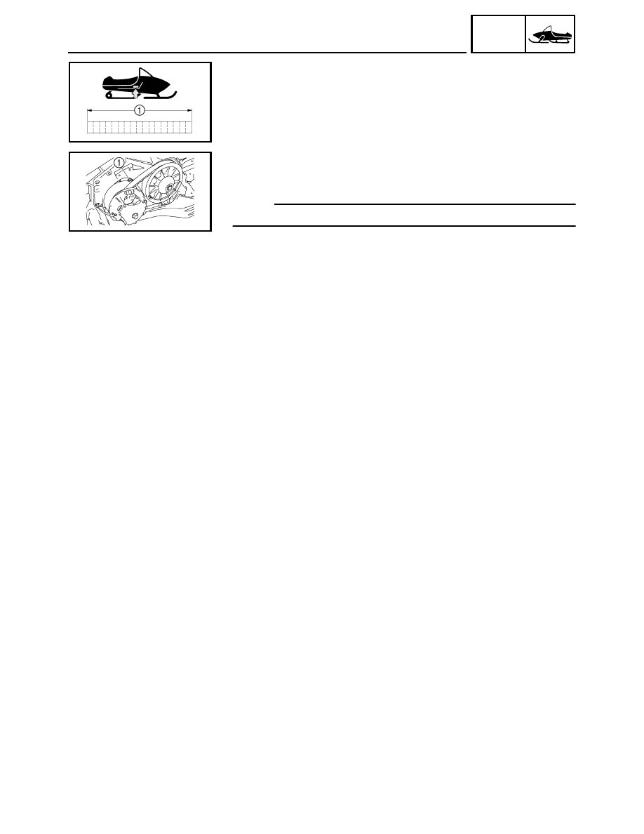
1-1

GEN

INFO

GENERAL INFORMATION

MACHINE IDENTIFICATION

FRAME SERIAL NUMBER

The frame serial number 1 is located on the right-hand side of the frame
(just below the front of the seat).

ENGINE SERIAL NUMBER

The engine serial number 1 is located on the left-hand side of the crank-
case.

NOTE:

Designs and specifications are subject to change without notice.

MACHINE IDENTIFICATION

1-2

GEN

INFO

IMPORTANT INFORMATION

IMPORTANT INFORMATION

PREPARATION FOR REMOVAL AND DISASSEMBLY

1. Remove all dirt, mud, dust, and foreign material before removal and

disassembly.
While cleaning, take care to protect the electrical parts, such as relays,
switches, motor, resistors, controllers, etc., from high pressure water
splashes.

2. Use proper tools and cleaning equipment. 

Refer to “SPECIAL TOOLS”.

3. When disassembling the machine, keep mated parts together. This

includes gears, cylinders, pistons, and other parts that have been
“mated” through normal wear. Mated parts must be reused or replaced
as an assembly.

4. During disassembly of the machine, clean all parts and place them in

trays in the order of disassembly. This will speed up assembly time and
help ensure that all parts are reinstalled correctly.

5. Keep all parts away from any source of fire.

6. Be sure to keep to the tightening torque specifications. When tighten-

ing bolts, nuts, and screws, start with those that have larger diameters,
and proceed from the inside to the outside in a crisscross pattern.

ALL REPLACEMENT PARTS

We recommend using genuine Yamaha parts for all replacements. Use oil
and grease recommended by Yamaha for assembly and adjustments.

1

1-3

GEN

INFO

IMPORTANT INFORMATION

GASKETS, OIL SEALS, AND O-RINGS

1. All gaskets, seals, and O-rings should be replaced when an engine is

overhauled. All gasket surfaces, oil seal lips, and O-rings must be
cleaned.

2. Properly oil all mating parts and bearings during reassembly. Apply

grease to the oil seal lips.

LOCK WASHERS/PLATES AND COTTER PINS

All lock washers/plates 1 and cotter pins must be replaced if they are
removed. Lock tab(s) should be bent along the bolt or nut flat(s) after the
bolt or nut has been properly tightened.

BEARINGS AND OIL SEALS

Install the bearings 1 and oil seals 2 with their manufacturer’s marks or
numbers facing outwards. (In other words, the stamped letters must be on
the side exposed to view.) When installing oil seals, apply a light coating
of lightweight lithium base grease to the seal lips. Oil the bearings liberally
when installing.

CAUTION:

Do not use compressed air to spin the bearings dry. This causes
damage to the surface of the bearings.

CIRCLIPS

All circlips should be inspected carefully before reassembly. Always
replace piston pin clips after one use. Replace misshapen circlips. When
installing a circlip 1, make sure that the sharp edged corner 2 is posi-
tioned opposite to the thrust 3 it receives. See the sectional view.

4 Shaft

LOCTITE

®

After installing fasteners that have LOCTITE

®

 applied, wait 24 hours

before using the machine. This will give the LOCTITE

®

 time to dry prop-

erly.

1-4

GEN

INFO

SPECIAL TOOLS

SPECIAL TOOLS

Some special tools are necessary for a completely accurate tune-up and
assembly. Using the correct special tool will help prevent damage that can
be caused by the use of improper tools or improvised techniques.

NOTE:

• Be sure to use the correct part number when ordering the tool, since the

part number may differ according to country.

• For USA and Canada, use part number starting with “YB-”, “YM-”, “YU-”

or “YS-”.

• For others, use part number starting with “90890-”.

FOR TUNE UP

• Dial gauge

P/N: YU-03097

90890-03097

This gauge is used for run out measurement.

• Angle gauge

Use goods on the market.

This tool is used to tightening the torque.

• Steering linkage alignment plate

P/N: YS-01515

90890-01515

Locks steering relay arm and pivot arm shaft in place while adjusting the
steering linkage for front-end alignment.

FOR ENGINE SERVICE

• Piston pin puller

P/N: YU-01304

90890-01304

This tool is used to remove the piston pin.

• Rotor holding puller

P/N: YU-33270-B

90890-01362

• Flywheel puller attachment

P/N: YM-33282

90890-04089

These tools are used to remove the magneto rotor.


Content   ..  1  2  3   ..