Snowmobile Polaris IQ (2007-2008 year). Manual - part 16


  Index      Snowmobiles / ATV     Snowmobile Polaris IQ - service manual 2007-2008 year


Search            


Content   ..  14  15  16  17   ..


Snowmobile Polaris IQ (2007-2008 year). Manual - part 16


3.4

Maintenance

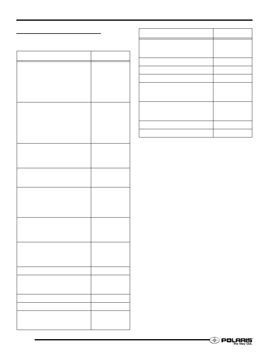
MAINTENANCE PRODUCTS

Engine Oils / Lubricants / Misc.

D

ESCRIPTION

P

ART

 N

UMBER

Premium 2-Cycle Oil
Quart
Gallon
2.5 Gallon
16 Gallon
55 Gallon
330 Gallon

2875035
2875036
2874037
2875038
2875039
2875040

VES Gold 2-Cycle Oil
Quart
Gallon
2.5 Gallon
16 Gallon
55 Gallon
330 Gallon 

2874438
2874439
2874443
2874440
2874441
2874442

Racing 2-Cycle Oil
Quart
Gallon
16 Gallon

2873025
2873023
2873919

PS-4 4-Cycle 0W-50 Oil
Quart
55 Gallon

2874865
2874867

PS-4 4-Cycle 2W-50 Oil
Quart
Gallon
16 Gallon
55 Gallon

2876244
2876245
2876247
2876246

Synthetic Chaincase Lubricant
Quart
Gallon
2.5 Gallon

2873105
2873106
2872952

Antifreeze 60/40 Premix
Quart
Gallon
55 Gallon

2871534
2871323
2872278

Shock Oil - 5W - Walker Evans

2874522

Shock Oil - Fox
Quart
Gallon

2870995
2872279

Shock Oil - Ryde FX / Arvin

2873716

Brake Fluid - DOT 4

2872189

Fogging Oil
Aerosol
Quart

2870791
2871517

Premium All Season Grease
3oz. Grease Gun Kit
14oz.

2871312
2871423

Starter Grease

2871460

Carbon Clean Plus

2871326

Isopropyl

2870505

Fuel Stabilizer
Quart
2.5 Gallon

2870652
2872280

Cross Shaft Assembly Lubricant
8oz.
2.5 Gallon

2872435
2872436

Three Bond Sealant 5oz.

2871557

Loctite 242

2871950

D

ESCRIPTION

P

ART

 N

UMBER

3.5

Maintenance

3

DRIVE / DRIVEN CLUTCHES

Belt Deflection Inspection

Too much belt deflection is when the belt is too long or the
center distance is too short. The initial starting ratio will be too
high, resulting in performance loss. This is due to the belt rising
too high in the drive clutch sheaves upon engagement (A).

Not enough belt deflection (B) is when the belt is too short or the
center distance is too long. The initial starting ratio will be too
low. In addition, the machine may creep when the engine idles,
causing damage to the internal face of the drive belt.

1.

Measure the belt deflection with both clutches at rest and
in their full neutral position.

2.

Place a straight edge across the tow clutches, on top the belt.

3.

Apply downward pressure to the belt and measure the
distance at point (D).

4.

The measurement should be 1 1/4" (3.2cm).

5.

If the measurement is not correct adjust driven clutch.

Deflection Adjustment - Team Driven

1.

Verify the drive system is FWD drive by rotating the
driven clutch forward.

2.

While holding the set screw with an Allen wrench, loosen
the jam nut.

3.

Turn the set screw clockwise while holding the jam nut
stationary to increase the distance between the clutch
sheaves (increase belt deflection).

4.

Turn the set screw counter-clockwise while holding the jam
nut stationary to decrease the distance between the clutch
sheaves (decrease belt deflection).

5.

Secure the jam nut while holding the set screw stationary.

6.

Raise the rear of the snowmobile using a track stand to
allow the track to spin.

7.

Start the engine and apply enough throttle to spin the track.

8.

Turn off then engine, then re-check the belt deflection.

NOTE:  Do not adjust the belt deflection to the point
where the drive belt cord line is visible when the belt
is seated in the driven clutch.

In. / mm. 

Belt Deflection: 1.25" (3.2cm)

3.6

Maintenance

Torque Stop Adjustment

Set torque stop bumper gap to specification after aligning drive
and driven clutches.

After setting gap, torque jam nut to specification.

NOTE: Where applicable, when installing a new
torque stop, position bumper so the tip is just
touching crankcase.

Engine Isolator Limiter Setting

Some models use an engine mount strap isolator. The isolator is
located on left-front corner of the bulkhead. The isolator should
not make contact with the engine strap.

If the isolator requires adjustment or replacement, hold the
isolator so it is against the bracket, then torque the nut to
specification.

NOTE:  Do not adjust this engine isolator limiter as a
torque stop or damage may occur. The approximate
distance from the face of the isolator to the face of
the engine strap is 0.107" (2.72mm).

In. / mm. 

Torque Stop Bumper-to-Engine Gap

.010 - .030 (.25 - .75mm)

T 

Torque Stop Jam Nut: 15-17 ft-lb. (21-24 Nm)

GAP

T 

Jam Nut: 15-17 ft-lb. (21-24 Nm)

ISOLATOR AGAINST BRACKET

BRACKET

NUT

ISOLATOR

3.7

Maintenance

3

ENGINE MAINTENANCE

Exhaust Valve Cleaning

The exhaust valve guillotines must be cleaned to ensure
maximum engine performance and throttle response.

1.

Remove the vent hose from the EV base fitting.

2.

Remove the two fasteners that secure the valve assembly
to the cylinder, but not the two screws that secure the cover
to the EV base.

3.

Carefully extract the guillotine out of the cylinder. Discard
the gasket.

4.

Using a clean rag or shop towel, remove the oil residue from
the cylinder, guillotine, and EV base.

5.

Inspect the guillotine for signs of damage. Replace
guillotine if damage is found, and inspect the cylinder and
piston for damage.

6.

Clean the guillotine with brake cleaner and a piece of fine
steel wool. Clean only to remove hardened carbon deposits.

7.

Once clean, rinse blade with mild detergent and water. Dry
completely.

8.

Install a new gasket, then reinstall the EV assembly. Apply
Loctite 242 to the fastener threads, then torque to
specification.

9.

Reconnect the vent hose.

NOTE: 

To obtain maximum exhaust valve

performance, Polaris recommends using Polaris
VES Gold Synthetic Two-Stroke engine oil.
Never mix different brands of engine oil. 

Surge Tank

Keep the level of the coolant inside the surge tank at the FULL
COLD level mark when the coolant is at room temperature.

Always add coolant when the cooling system is COLD.

Recommended Coolant

Use Polaris Premium 60 / 40 pre-mix antifreeze. This premium
antifreeze is rated for temperatures down to -62°F (-52°C). 

Cooling System Bleeding

1.

Allow the cooling system to cool completely.

2.

Verify the coolant level in the surge tank is at the COLD
mark. Fill the surge tank if required. Loosely install the
pressure cap.

3.

Open the thermostat housing bleed screw. Wrap a clean
shop towel around the housing to absorb any coolant that
may flow out of the bleed screw.

4.

Elevate the front of the machine slightly.

5.

Apply the parking brake and start the engine.

6.

Allow the engine idle time to stabilize.

7.

Immediately add coolant to the surge tank if the coolant
level dropped significantly after the engine started. Watch
the level and add more coolant until the level stops
dropping.

NOTE:  Squeeze the coolant hoses to purge air from
the cooling system.

8.

Secure the pressure cap and bleed screw after the
thermostat begins to open and coolant begins to flow out
of the bleed screw.

9.

Verify the tunnel coolers begin to warm up as the engine
continues to run.

10. To remove air from the tunnel cooling system, the vehicle

should be pivoted upwards in four directions (nose up, left
side up, rear bumper up, and right side up) to move any air
pockets in the system to the surge tank.

T 

Exhaust Valve Housing Fasteners

12 Ft.Lbs. (16 Nm) - Apply Loctite 242

GASKET

EV ASSEMBLY

FASTENERS

CAUTION

Never remove the surge tank pressure cap when the cooling 

system is warm. Severe burns to skin may occur from escaping 

coolant or steam.


Content   ..  14  15  16  17   ..