Snowmobile Polaris Two Stroke (2007 year). Manual - part 35
5.33
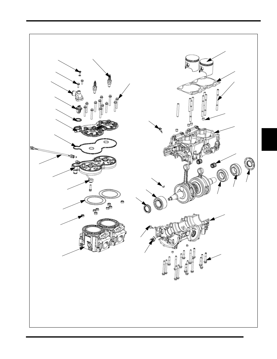
ENGINE
5
600/700 CFI Engine Disassembly
1
2
5
3
6
7
9
10
11
12
13
14
15
16
18
19
20
21
24
27
28
26
31
32
29
25
23
17
4
8
22
30
If new see
installation
height on
page 5.5
|
|
|
5.33 ENGINE 5 600/700 CFI Engine Disassembly 1 2 5 3 6 7 9 10 11 12 13 14 15 16 18 19 20 21 24 27 28 26 31 32 29 25 23 17 4 8 22 30 If new see installation height on page 5.5 |