Snowmobile Polaris Two Stroke (2007 year). Manual - part 30


  Index      Snowmobiles / ATV     Snowmobile Polaris Two Stroke - service manual 2007 year


Search            


Content   ..  28  29  30  31   ..


Snowmobile Polaris Two Stroke (2007 year). Manual - part 30


5.13

ENGINE

5

1.

Disconnect the coil pack and CDI from the wiring harness.

2.

Loosen the carburetor clamps (1) and remove the
carburetors from the mounting boots.

3.

Note where the oil lines are routed and remove the oil lines
from the carburetors.

4.

Remove the carburetor mounting boots (2) from the
cylinders.

5.

Remove both the cylinder head (3) and the exhaust side fan
(4) shrouds from the engine assembly.

• 340 has a intake side shroud

6.

After removing the fan shrouds, take note of the vibration
dampener (5) located between the cylinders intake side
(550 only).

7.

Remove the recoil cover (6).

8.

Remove the recoil cup (7).

9.

Hold the flywheel with the holding wrench PN 8700229
and remove the flywheel nut and washer.

10. Using a flywheel puller (PN 2871043), remove the

flywheel (8) from the engine. Do not install the puller bolts
in amy more than 5/16” of an inch/7.9mm into the flywheel
threads or stator damage may result.

11. Remove the flywheel.

12. Remove the blower housing that the stator is mounted too. 

NOTE:  Make sure to account for the dowels on the
blower housing (550 only).

13. Remove the oil pump (9). Note the o-ring and shim

placement.

14. Remove the cylinder head bolts (10).

15. Remove the cylinder head (11).

16. Remove the head gasket (12). During the removal process

note that the gasket has a EX for exhaust side and UP for
the orientation.

17. Remove the cylinder base nuts (13) and carefully remove

each cylinder (550 only)

18. Remove the reed valve assembly (14) from the crankcase

(550 only).

19. Remove the wrist pin c-clips

20. Using a piston pin puller (PN 2870386) remove the wrist

pins from the pistons.

21. Turn the crankcase over and remove the crankcase bolts

(15).

22. Carefully turn the case back over and separate the case

halves.

23. Remove the crankshaft and crankcase seals (16).

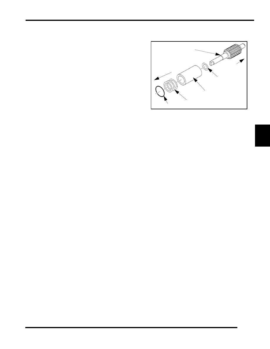
24. Remove the oil pump bushing, spacer, and cross shaft (17)

and inspect for any wear or damage.

Engine Assembly

1.

Insert the oil pump cross shaft, spacer and bushing.

2.

Install a new o-ring on the oil pump.

3.

Place the oil pump aside for later installation.

4.

Set the crankshaft into the lower case half.

5.

Grease the oil pump drive gear area.

NOTE: 

Make sure that the crankshaft rotates

smoothly and does not bind. Rotate the bearings so
that the anti-rotation pins are resting in their
appropriate galleries.

6.

Apply 3-Bond (PN 2871557) sealer to the top half of the
crankcase.

7.

Install new crankcase oil seals with spring and lip facing
inward toward the crank bearing.

8.

Match up the top half of the crankcase to the lower case and
hold the case halves together and turn it upside down.

Gear

Spacer

Bushing

Spacers

o-ring

Engine side

Oil Pump Side

5.14

ENGINE

9.

Install the crankcase bolts and torque to (550 = 15-18 ft-lb
(25 N-m) (340 = 8mm -23 to 25 N-m, 10mm - 32-35 N-m)
in the pattern shown below.

10. Turn the crankcase over and lubricate crankshaft main

bearings through the access holes.

11. Apply Polaris 2-Stroke engine oil to the wrist pins and the

small end bearings and install the pistons with the arrow on
the piston crown facing the flywheel (MAG) side. This will
orientate the piston so that the piston ring locating pins will
be in the intake side of the engine. Install wrist pins onto
the crankshaft with the piston installation tool (PN
2830386).

12. Lubricate rings and the pistons with Polaris 2-Stroke oil and

install the rings with the letter, mark or beveled side facing
upward.

13. Install the c-clips into the piston so that the opening of the

“C” is positioned at the 12:00 or 6:00 position.

14. Install the reed valves in to the intake of the crankcase.

15. Install new base gaskets.

16. Compress the piston rings and install each cylinder onto the

crankcase.

17. Torque the cylinder base nuts to: 

18. Install a new head gasket with the “EX” facing the exhaust

side. Also make sure that the “UP” is facing the intake side
of the engine. (550 only)

19. Insert the head bolts and torque to:

20. Insert the dowels on the blower housing that match up with

the crankcase (550 only).

21. Route the stator wires harness correctly.

22. Install the flywheel, lock washer, woodruff key, and

flywheel nut onto the shaft.

T 

550 Crankcase Bolts 15-18 ft.lb. (20-25 N-m)

340 Crankcase Bolts: 8mm=17-18 ft-lb (23-25N-m)

10mm=24-26 ft-lb (18-19 N-m)

9

5

1

12

8

4

3

2

7

6

11

10

CRANKCASE TORQUE PATTERN-FUJI

13

14

550 only

T 

340 = 17-18 ft.lb. (23-25 N-m)
550 = 25-30 ft.lb. (34-40 N-m)

T 

340 = 18-21 ft.lb. (25-28 N-m)
550 = 17-21 ft.lb. (23-28 N-m)

CYLINDER BASE TORQUE PATTERN-FUJI

1

3

4

2

CYLINDER HEAD TORQUE PATTERN-FUJI

1

3

4

2

5

3

2

1

4

6

550

340

5.15

ENGINE

5

23. Torque the flywheel nut to:

24. Install the recoil cup onto the flywheel.

25. Install the recoil cover.

26. Insert the vibration dampener in between the cooling fins

that are located between the two cylinders on the intake
side.

27. Install the fan shrouds.

NOTE: Make sure that the fan deflectors interlock
before tightening down.

28. Install the oil pump onto the lower case half.

NOTE:  Install all oil pump shims.

29. Apply Blue Loctite 243 to the oil pump mounting screw

threads and torque to 48-72 in-lb (5.5-8.3 N-m).

30. Route each oil line on the oil pump in the correct positions.

31. Install intake boots (340 only).

32. Install the boot clamps onto the boots.

33. Install the carburetors onto the boots.

34. Tighten the boot clamps.

35. Insert engine into the chassis.

T 

340 = 61-70 ft.lb. (83-90 N-m)
550 = 58-72 ft.lb. (79-98 N-m)

T 

Oil Pump Mounting Screw Torque: 48-72 in-lb

 (5.5-8.3N-m)

5.16

ENGINE

500 FUJI ENGINE

For engine removal See “340/550 Fuji/500 Liberty Engine
Removal/installation” on page 5.11.

Disassembly

NOTE: Inspect all parts for wear or damage during
disassembly. Replace all seals, O-rings, and gaskets
with Genuine Polaris parts during assembly. Refer to
General Section for Inspection Procedures.

1.

Remove carburetors, recoil housing and exhaust manifold.

2.

Remove water pump, and starter recoil cup with water
pump drive pulley and flywheel nut.

3.

Install flywheel puller PN 2871043. Use all flywheel bolt
holes. Do no install puller bolts more than 5/16" (7mm) into
flywheel or stator damage may result.

4.

Mark stator plate and crankcase for reference when
reassembling the engine.

5.

Using a screwdriver, remove stator screws.

6.

Remove oil pump, oil pump feed lines from cylinders.
Clean and inspect all components.

7.

Remove the cylinder head.

8.

Remove head gasket. Note the position of head gasket inlet
and outlet hole sizes for reference during reassembly.
Always replace head gasket after disassembly.

9.

Remove cylinder.

10. Remove C-clip retainers from pistons.

11. Using piston pin puller, remove piston pin from piston.

12. Remove crankcase bolts. 


Content   ..  28  29  30  31   ..