Snowmobile Polaris PRO X (2003 year). Manual - part 73


  Index      Snowmobiles / ATV     Snowmobile Polaris 440 PRO X Fan, 440 PRO X, 600 PRO X, 700 PRO X, 800 PRO X - service manual 2003 year


Search            


Content   ..  71  72  73  74   ..


Snowmobile Polaris PRO X (2003 year). Manual - part 73


ELECTRICAL

8.14

Ignition Switch Testing (Non-Electric Start)

1.

Set the multitester dial to the ohms (

:) position.

Connect one of the tester leads to either of the switch
terminals and the other tester lead to the other switch
terminal.

2.

With the switch off, the reading should be less than .4
ohms. With the switch on, the reading must be an open
circuit (OL).

3.

Check the resistance between each of the switch
terminals and the switch body. With the switch still in the
on position, there must be an open circuit (OL) reading.
Readings other than those listed indicate a defective
switch.

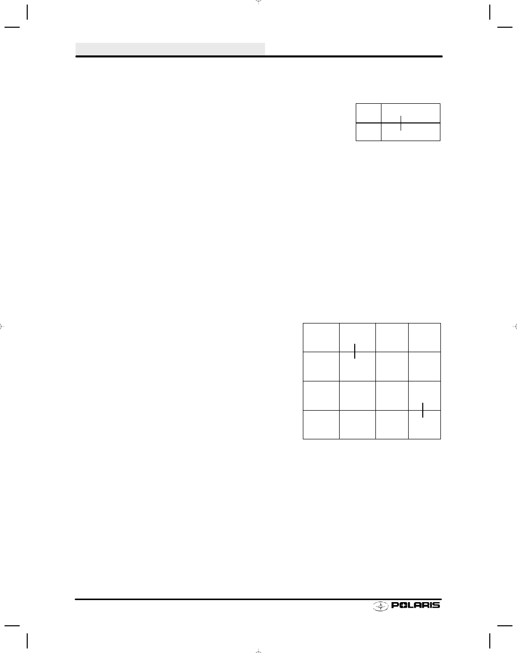
Ignition Switch Testing (Electric Start Models)

NOTE: Refer to the appropriate model and year wiring
diagram for ignition switch wire colors and connections.

1.

Disconnect wires. Set the multitester dial to the ohms
(

:) position.

2.

With the key in the off position, check the resistance
between the G (Ground, brown) terminal and the M
(Mag, black) terminal. This reading must be less than .4
ohms.

3.

Turn the key to the on position. The multitester should
now read an open circuit (OL).

4.

Move the tester lead from the G terminal to the switch
housing and re-check the reading. It should also be an
open circuit (OL).

5.

Place one of the tester leads on the B (Battery, red)
terminal and the other tester lead on the S (Starter, blue)
terminal. With the key in the on position, there must be
an open circuit (OL) reading.

6.

Turn the key to the start position. The reading should be
less than .4 ohms. Readings other than the ones listed
indicate a defective switch.

Blk

Brn

Off

On

Ignition Switch

D

D

Brn

Blk

R

R/W

Off

On

Start

D

D

D

D

Ignition Switch - Electric Start

ELECTRICAL

8.15

Coolant High Temperature Indicator Testing

Lamp Circuit Test

1.

Remove wire from temperature sensing switch located under thermostat housing.

2.

With engine idling, ground wire to engine. The temperature warning lamp on the console should light. If not,
replace the lamp assembly or inspect wiring for shorts or open circuit.

Temp Light Temperature Sensor Test

The temperature/warning switch is normally open.

1.

Set the multitester on the ohms (

:) scale.

2.

Disconnect the lamp wire.

3.

Connect one test probe to the switch terminal and the other to engine ground. The meter should show an open
circuit (OL). This indicates a normally open switch. If the switch were heated to approximately 205

q F, the

contact in the switch would close and the reading would be less than .4 ohms.

CAUTION:

If attempting to heat the sensor to close the contacts, heat only in a water bath. Never subject the sensor to an
open flame to attempt to close the contacts as sensor damage will result.

Polaris DRAGONIgnition Operation

Your 2003 Polaris 440 Pro--X snowmobile is equipped with an ignition--system feature which improves competi-
tion performance by increasing exhaust--system temperature. The Dragont ignition system provides maximum
”holeshot” performance for racing applications.

WARNING: Dragon mode in creases the exhaust--system temperature and causes engine misfire and backfire.
Flammable materials and vapors can be ignited resulting in fire and explosion which may cause serious injury,
death, or property damage. Read Owner’s Manual. Always follow all instructions and warnings.

Additional information regarding Dragon mode operation:

S

The Dragont ignition system is intended for competition use only.

S

There is no benefit to using Dragon mode for normal trail riding.

S

Unnecessary, extended, or excessive use of Dragon mode can result in severe engine damage
which is excluded from Polaris Warranty coverage.

S

Dragont mode usually heats up the exhaust system within 5 to 20 seconds, depending upon
the initial temperature of the exhaust system.

S

Two different sounds may be heard when using Dragont mode. One sound is an erratic misfire
heard when the exhaust system is heating up. The other sound is a consistent misfire (with a
slight rise in engine RPM) when the exhaust system is at target operating temperature.

S

Dragont mode keeps the engine speed to between 4500 and 5100 RPM.

S

Be sure that the clutch engages at 5300 RPM or above to prevent forward creep of the vehicle.
See your dealer if clutch needs to be adjusted.

To use Dragont mode at the start of a race:

1.

Warm up the engine and track using the procedure in the Owner’s Manual.

2.

When staged at the starting line, depress and hold the Dragon (horn) button.

3.

Slowly advance the throttle to the wide--open position while keeping the button depressed.

4.

Release the button when the start flag drops.

5.

The vehicle will launch forward at wide--open throttle.

ELECTRICAL

8.16

Speed Control Assurance Operation

A

B

Off Idle Switch

Idle Switch

Plungers
Outward

Throttle Control
Cutaway

Engine Ground

Ignition Primary

Auxiliary Kill
Switch Contacts

Insulator

Conductor

The speed control assurance consists of two series connected switches. If one or both switch plungers are posi-
tioned inward, the circuit is open and the engine will run.

At idle, with the throttle lever properly adjusted, the bottom switch circuit is open and the plunger is inward. The
top switch circuit is closed, and the plunger is outward. The speed control circuit is open, allowing the engine to
run.

As the throttle lever is actuated to an off idle position, the top switch circuit is opened (plunger in) and the bottom
switch circuit is closed (plunger out). The speed control circuit is still open, allowing the engine to run.

In the event the carburetor or controls malfunction and allow the throttle cable to become slack, the circuit will
close (both switch plungers out), grounding the ignition system and causing the engine to stop.

Speed Control Assurance Adjustment

Throttle lever free play must always provide a specified
clearance between throttle lever (A) and throttle block (B).
This clearance is controlled by the throttle cable sleeve(s)
and the idle speed screw(s).

If the idle speed screw(s) is adjusted inward and the cable
sleeve(s) is not adjusted to take up the throttle lever to
throttle block clearance, the engine may misfire or kill upon
initial throttle opening.

CAUTION:

After any idle speed adjustments are made, the throttle lever to throttle block clearance and oil pump adjustment
must be checked and adjusted.

NOTE: When adjustments are made on models which have more than one carburetor, refer to Section 6, Car-
buretion, for proper carburetor synchronization adjustments.

.010-.030

s (.25-.8 mm)

Throttle Lever Freeplay -

Regular Throttle - .010 - .030

(.25 - .8 mm)

ELECTRICAL

8.17

Speed Control Assurance Testing

1.

Set the multitester in the ohms (

:) position.

2.

Disconnect the switch harness from the main wire harness.

3.

Connect the two multitester leads to the two switch wires.

Test 1 - Open Circuit - Run

With the auxiliary shut-off switch in the ON position, the
multitester should read an open circuit (OL). As the throttle
lever is moved from idle to off idle, the tester should continue
to read an open circuit. If the tester fluctuates and the
throttle lever to throttle block clearance is adjusted properly,
the switch assembly must be replaced.

Test 2 - Closed Circuit - Kill

The two speed control switches must make a complete cir-
cuit to kill the engine. To check the switches, pull the throttle
lever out away from the throttle block. With the switch plung-
ers outward and the auxiliary shut-off switch in the ON posi-
tion, the multitester must read less than .4 ohms resistance.
Inspect wires and repair if damaged, or replace switch as-
sembly.

Test 3 - Auxiliary Shut-Off

The multitester should read less than .4 ohms in the OFF position and an open circuit in the the ON position.
Inspect wires and repair if damaged, or replace switch assembly.

Speed Control Assurance Replacement

Auxiliary shut-off and speed control assurance switches are connected and replaced as a unit from the back side
of the throttle block.

1.

Remove the handlebar pad and/or throttle block backing plate.

2.

Slide out the auxiliary shut-off portion of the switch.

3.

Remove the two screws securing the two speed control assurance switches.

4.

Remove the switches noting their placement in the throttle block.

5.

Replace the assembly and check its operation.


Content   ..  71  72  73  74   ..