Snowmobile Polaris PRO X (2003 year). Manual - part 40
CLUTCHING
4.28
Assembly, Cont.
5.
Install spring and cover. Torque cover bolts evenly to
specification.
CAUTION:Carefully align bushing with shaft during
installation of cover to prevent bushing damage. Maintain
alignment by tightening cover bolts evenly and carefully.
Installation
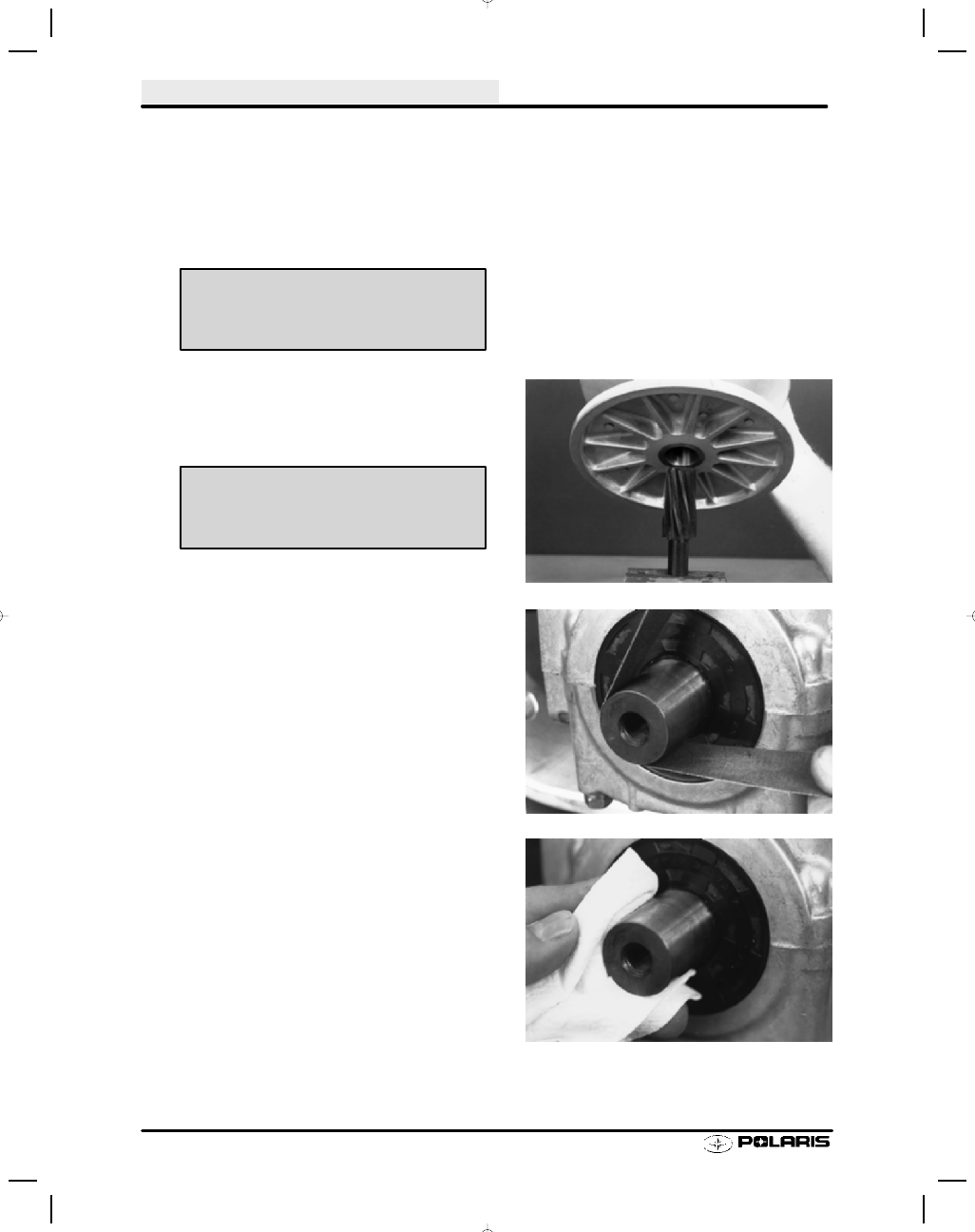
1.
Slight galling or scoring of the bore taper can usually
be corrected using a tapered reamer. Place reamer in
a vise and lubricate with cutting oil. Clean taper by
manually rotating clutch clockwise.
2.
Check crankshaft taper for galling or scoring. If
necessary clean taper evenly with 200 grit emery
cloth.
3.
Both clutch taper and crankshaft taper should be
clean and dry.
NOTE: Do not use harsh cleaners which may cause
clutch taper to corrode during use. This will cause diffi-
culty when removing clutch in future. Clean clutch taper
with lacquer thinner or isopropyl alcohol.
Spider Cover Bolt Torque -
90 in. lbs. (10 Nm)
Tapered Reamer PN 2870576