Snowmobile Polaris EDGE / WIDETRAK (2007-2012 year). Manual - part 46


  Index      Snowmobiles / ATV     LX Snowmobile Polaris EDGE / WIDETRAK - service manual 2007-2012 year


Search            


Content   ..  44  45  46  47   ..


Snowmobile Polaris EDGE / WIDETRAK (2007-2012 year). Manual - part 46


7.16

PVT System

9923396 - 2007-2012 EDGE/Widetrak LX Service Manual

©2011 Polaris Sales Inc.

PVT SYSTEM ADJUSTMENTS

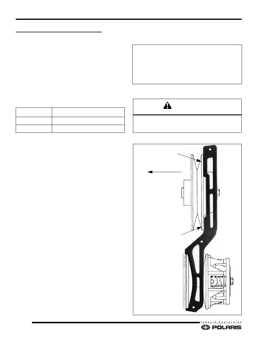
Clutch Alignment / Offset

The engine is mounted in the bulkhead so the drive and
driven clutches self-align under high torque loads.

Offset is controlled by the number of washers installed on
the jackshaft behind the driven clutch.

1.

Remove drive belt.

2.

Install the correct alignment tool depending on the
type of driven clutch installed on the snowmobile.

NOTE:  A standard alignment tool will not work with a
Team LW driven clutch. Likewise, a LW alignment tool
will not work with a standard Team driven clutch.

3.

The optimum setup is when the front and rear of the
tool touch the driven clutch. No gap should be present
in the front, and the rear clearance should not exceed
.060" (3mm).

NOTE:  If the front of the alignment bar does not touch
the driven sheave, the maximum clearance cannot
exceed .025

.

Offset/Float Adjustment

1.

Determine direction driven clutch needs to be
adjusted.

2.

Remove driven clutch retaining bolt, and remove
driven clutch.

3.

With one 16 GA. bushing installed, add or remove
offset washers from behind the driven clutch to set the
proper offset.

4.

After adjusting the offset, add or remove shim
washers from behind the driven clutch bolt and
washer to provide a .060" (.1.5mm) driven clutch float
on the jackshaft.

AR = As Required

tool part number

application

PS-46998

Standard Team Driven

PS-47477

Light Weight (LW) Team Driven / P2

Driven Clutch Offset/Shim Washers

Offset Washers

16 Gauge Bushing=7556509 (QTY.1)

.023” = 7555917 (AR)
.120” = 7555864 (AR)

Float Washers

.065" = 7555806 (AR)
.105" = 7555832 (AR)

CAUTION

Always verify the driven clutch floats on the jackshaft. 

The jackshaft bearing will fail from side-loading if the 

driven clutch is not allowed to float.

0” - .060”

TOUCHING

(PN: PS-46998 Shown)

PUSH CLUTCH

7.17

PVT System

7

9923396 - 2007-2012 EDGE/Widetrak LX Service Manual

©2011 Polaris Sales Inc.

DRIVE CLUTCH

Identification

Every clutch will have the last three digits of the clutch part
number etched on to the cover (A). The “X" (B) marking is
an index mark where the clutch cover (C), clutch spider (D)
and the stationary sheave (E) should line up when the
clutch is assembled.

Drive Clutch Removal 

NOTE:  All clutch tools can be found at the beginning 
of this chapter. 

1.

Remove the belt.

2.

Place the clutch holding tool (PN 9314177-A) on the
drive clutch.

3.

Remove the drive clutch retaining bolt. Note the
placement and number of washers on retaining bolt.

4.

Insert the correct clutch puller into the retaining bolt
hole.

5.

Tighten the puller into the clutch. If the clutch does not
come off, strike the clutch puller head with a hammer.
If the clutch does not “pop” off, continue to tighten the
clutch puller, and repeat this step.

A

B

C

D

B

E

CAUTION

Do not use an impact wrench to remove or install the 

clutch bolt or clutch puller. Damage to the clutch and/or 

crankshaft can occur.

7.18

PVT System

9923396 - 2007-2012 EDGE/Widetrak LX Service Manual

©2011 Polaris Sales Inc.

Drive Clutch Disassembly

1.

In a straight line, mark/etch the sheaves and the cover
with a black marker or a scribe.

2.

Place the drive clutch in the clutch compression tool
(PU-50518), or similar clutch compressor tool.

3.

Evenly remove the cover fasteners. The cover
bushing may be damaged if the cover is side-loaded
or mis-aligned.

4.

Carefully remove the tension from the compression
tool.

5.

Remove the cover and inspect the cover bearing.
Replace if damaged or worn.

NOTE: Replace the cover bearing if the inside
diameter is over 1.40

 (28.95mm)

6.

Remove the spring.

7.

Mount the drive clutch securely in a drive clutch
holding fixture (PN 2871358-1).

8.

Remove the jam nut in a counterclockwise direction

(standard thread) using the drive clutch spider nut
socket (PN 2870338).

9.

Install the spider removal tool (PN 2870341), and
remove the spider in a counterclockwise direction
(standard thread).

10. Measure the total thickness of the spacer washers

that are installed on top of the clutch spacer. Record
the thickness of these spacer washers. Note the .130
clutch spacer and that the washers sit on top clutch
spacer.

11. Inspect both sheave surfaces for wear or damage.
12. Inspect the moveable sheave bushing for wear or

damage.

13. Remove all three drive clutch weights.
14. Inspect each weight. The roller surface should be

smooth, with no waves or galling. Place bolt inside
weight to check flyweight bushing and pin surface for
wear by rocking the weight back and forth.

15. Inspect the rollers, bushings and roller pins by pulling

a flat metal rod across each roller.

16. Roller can also be inspected by rolling with a finger to

feel for flat spots, roughness, or loose bushing.

NOTE: The flyweight bushing is not replaceable. If
flyweight bushing is damaged both the flyweight, pin
and nut will need to be replaced. 

17. Inspect to see if the roller and bushing are separating.
18. Bushing must fit tightly in roller.
19. Replace roller and pin if roller fails to roll smoothly (no

flat spots) or if the bushing is loose or worn.

STATIONARY SHEAVE

MOVEABLE SHEAVE

SPIDER

COVER

SPRING

JAM NUT

SPACERS

CLUTCH SPACER

BEARING SLEEVE

MOVEABLE INSERT

COVER BEARING

RETAINER

SPIDER BUTTON

WASHER

ROLLER

ROLLER PIN

SHIM

WEIGHT

WEIGHT PIN

CAUTION

Wear eye protection when servicing the drive clutch.

Sheaves must be marked to provide a reference point 

for dutch balance and spider indexing. If the sheaves 

are not marked and the spider washers are changed or 

misplaced, the clutch may be out of balance and 

damage to the clutch may result. 

WARNING

Clutch spring is under extreme tension, use caution 

when disassembling the clutch.

7.19

PVT System

7

9923396 - 2007-2012 EDGE/Widetrak LX Service Manual

©2011 Polaris Sales Inc.

Roller Removal

1.

With the spider in a vise start removing the spider
buttons by drilling a 0.18" hole in the center of a button
on one side of the spider.

2.

Place spider on a vise or in an arbor press.

3.

Place a pin punch through the drilled hole in the button
and drive the opposite button and pin out.

4.

Remove shims (if any are installed) and note their
location.

5.

Flip the spider over and tap out the holed button.

6.

Perform steps on remaining spider legs.

NOTE:  When required, button shims are installed on
the trailing (right) side of the spider leg as viewed from
the front of spider.

Roller Installation

NOTE:  CAUTION: Use care to start the pin straight.
Aluminum burrs could pass through into the roller
bushing causing it to bind and stick. Also use care to
make sure the roller remains aligned when the pin is
driven through. The roller busing could be damaged
causing premature wear and roller failure.

1.

Drive pin into the spider leg .100" -.125" (0.25 -
0.32cm) beyond the first land of the spider leg.

2.

Install one washer on the portion of the pin that is
protruding from the spider leg.

3.

Place roller in spider leg and center it on the pin.

4.

Place a second washer on the other side of the roller.

5.

Place the spider on a vise.

6.

Install pin centering tool (PN 2870910-A or 8700221).

7.

Drive the roller pin through the second land of the
spider.

8.

Repeat process for the other two rollers.

Spider Button Installation

1.

A shim kit is available which contains an assortment
of shims.

2.

Measure the width at the base of the moveable
sheave towers and record.

3.

Measure the width of each corresponding spider leg
with the buttons installed and record.

4.

Subtract the spider measurement form the tower
measurement. The clearance between the spider
buttons and the moveable sheave towers is .001-
.002" (0.025-0.05mm).

5.

Add shims beneath each trailing side spider button to
obtain the specified button-to-tower clearance when
assembled at each spider leg.

SPIDER

BUTTON

SHIM

WASHER

ROLLER

ROLLER PIN

WASHER

BUTTON

Drive Clutch Shim Kit

PN 2200387

In. / mm. 

Button-To-Tower Clearance
.001"-.002" (0.025-0.05mm)


Content   ..  44  45  46  47   ..