Kincaid 8xp. Manual - part 4
- 19 -
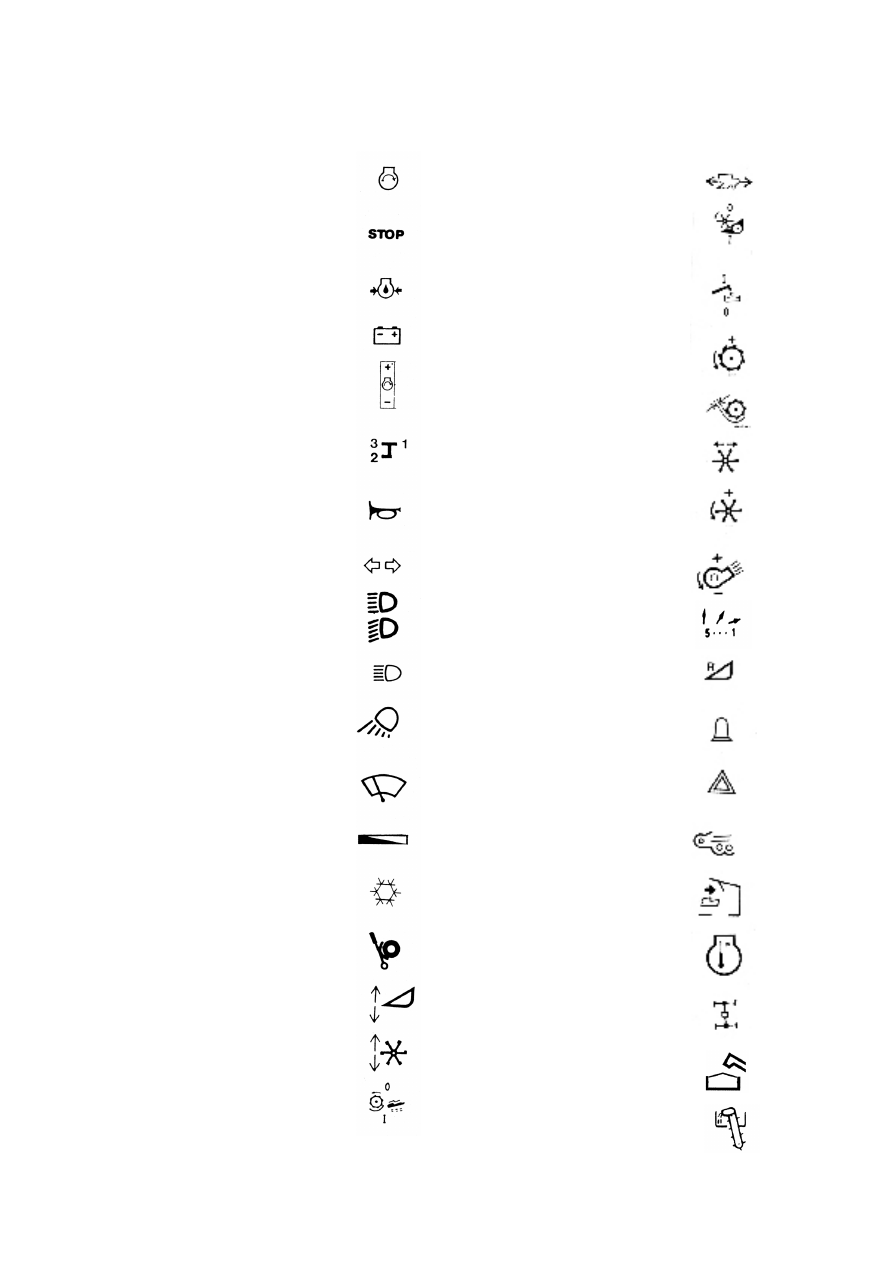
Signs and Symbols
Ignition Lock / Starting
Stop Control
Oil Pressure Warning Light
Alternator Warning Light
Throttle Control
Gear Change Decal
Horn Button
Flashers
Anti-dazzle Switch
Headlights
Working Lights
Windscreen Wipers
Cabin Heating Control
Air Conditioning Control
Parking Brake
Table Height Control
Reel Height Control
Engage of Threshing unit
Speed Control Lever
Engage of Cutting Table
Grain Tank Unloading
Cylinder Speed
Concave Clearance
Reel Fore & Aft Control
Reel Speed Control
Cleaning Fan Speed Control
Cleaning Air Direction
Reversing of Cutting Table
Rotating Flasher
Emergency Flasher
Return Alarm
Straw Alarm
Coolant Temperature Alarm
Four-Wheel Drive
Full Grain Tank
Grain Elevator Alarm