Challenger Terra Gator 3244 Chassis. Manual - part 126


  Index      Challenger     Challenger Terra Gator 3244 Chassis - service repair manual 2009 year


Search            


Content   ..  124  125  126  127   ..


Challenger Terra Gator 3244 Chassis. Manual - part 126


627333-A  

8-11

Air Dryer

AIR DRYER COMPONENTS

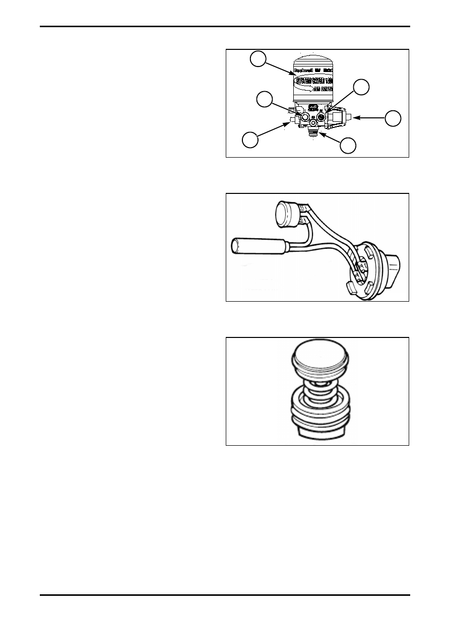
FIG. 5: Air dryer assembly.

(1)

Heater

(2)

Turbo Cut-off Valve

(3)

Desiccant Cartridge

(4)

Outlet Check Valve

(5)

Regeneration Valve

(6)

Purge Valve

Heater

FIG. 6: Heater is located in air dryer base. Heater

prevents water that collects in air dryer from freezing.

The heater consists of a cylindrical resistive-type

heating element and small circular thermostat. Heater

is 12-volt.

To replace heater, disconnect electrical plug. Remove

screws, receptacle and O-ring from base to access

retainer screw. Remove entire screw and remove entire

heater assembly. Install new element and thermostat in

cavities. Install new retainer and screw to hold element

and thermostat in place. Install new O-ring and

receptacle and fasten in place with screws.

Turbo Cut-off Valve

FIG. 7: Turbo cut-off valve is located in inlet port of air

dryer. The turbo cut-off valve closes path between air

compressor and air dryer purge valve during

compressor unload. This prevents a loss of

turbocharger boost pressure during a compressor

unload cycle, keeping boost pressure for maximum

engine horsepower.

IMPORTANT: There is no spring in the turbo cut-off

valve assemblies used on U Series air dryers.

To replace turbo cut-off valve, remove snap ring. Cover

and spring may fall out of bore. Remove desiccant

cartridge. Use a wooden stick to push piston spring and

cover out if they don’t fall out. Clean and inspect the

valve bore. If bore is damaged so that a tight seal

cannot be maintained, replace air dryer.

Install new lip seal on piston. Seal lip must face up

toward top of piston. Install new O-ring on cover. Use

grease supplied with kit to apply thin film to valve bore

and O-ring. Install new piston with flat side toward

dryer. Install new spring, cover, and snap ring to hold

components in place. Install plug. Replace desiccant

cartridge.

FIG. 5

M6205002

1

4

6

5

2

3

FIG. 6

M6215001

FIG. 7

M6215002

Air Dryer

8-12

627333-A  

Desiccant Cartridge

FIG. 8: Desiccant cartridge is a steel housing

containing filter elements needed to filter and dry

system air.

m

WARNING: To prevent serious eye injury,

always wear safe eye protection when

you perform vehicle maintenance or

service. Remove all pressure from the air

system before you disconnect any

component, including the desiccant

cartridge. Pressurized air can cause

serious personal injury.

Replace cartridge by turning cartridge

counter-clockwise to unscrew from air dryer. Screw

new desiccant cartridge onto air dryer by turning

clockwise until tight.

Outlet Check Valve

FIG. 9: Outlet check valve is located in outlet port.

Outlet check valve prevents air from flowing back

through air dryer and escaping out purge valve during

compressor unload cycle.

To replace outlet check valve, remove snap ring,

washer, spring, valve body, and O-ring. Clean and

inspect the valve bore. If bore is damaged so that a

tight seal cannot be maintained, replace air dryer.

Install new O-ring on valve body. Use greased supplied

with kit to apply thin film to valve bore and O-ring. Install

new valve body with its long end in bore. Install new

spring with its small end around the Y-shaped fins on

the valve body. Install new washer and snap ring to

hold components in place.

Regeneration Valve

FIG. 10: Regeneration valve controls regeneration of

desiccant. Regeneration valve allows air from supply

and secondary tanks to bypass outlet check valve. Air

expands and backflushes moisture off of desiccant,

then out through dryer purge valve.

Regeneration valve assembly kit contains two different

diaphragms to service regeneration valve assembly for

System Saver 1000, 1200, or 1800 air dryers. Use

correct diaphragm for style of regeneration valve

housing.

IMPORTANT: Using incorrect part will result in

unsatisfactory purging of desiccant cartridge

and may result in excess water in air system.

IMPORTANT: Smooth diaphragm is used with smooth,

cylindrical regeneration valve housing. The

speckled/dotted diaphragm is used with

finned/ribbed die cast housing. Only one

diaphragm is used per assembly. DO NOT

GREASE THE DIAPHRAGM.

FIG. 8

M6215003

FIG. 9

M6215004

FIG. 10

M6215005

627333-A  

8-13

Air Dryer

Remove four mounting bolts and valve housing

assembly. Spring and cap will fall out. Remove rubber

diaphragm. Clean and inspect diaphragm lip groove. If

groove is damaged so that a tight seal cannot be

maintained, replace air dryer. Install new diaphragm

with its lip in groove. DO NOT GREASE THE

DIAPHRAGM.

Install new spring and cap with cap lip facing out. Install

valve housing assembly with new lubricated O-ring and

filter over orifice. Install new mounting bolts and tighten

to 6 Nm (53 lbf in).

Purge Valve

FIG. 11: Purge valve is located on bottom of air dryer.

Purge valve remains open during a compressor unload

cycle. Purge valve allows collected moisture,

condensation, and contamination to be expelled from

air dryer during purge cycle.

The purge opens by gouvenor when the pressure

inside the tanks is to high. The pressure can be edit by

adjusting the purge valve.

Use grease included with replacement kit to lubricate

O-rings and seals. DO NOT grease rubber seat. If

shims are included in replacement kit, they must be

installed above and below spring. If they are not

included, they are not needed. Remove snap ring,

valve head and spring. Remove piston assembly from

base. Remove washer and O-rings from base. Clean

and inspect valve bore. If valve bore is damaged so

that a tight seal cannot be maintained, replace air dryer.

Apply a thin layer of grease to valve bore and to all

O-rings. Install new washer and O-ring in dryer base

and on valve head. Assemble piston assembly. Install

O-ring in groove on piston head. Install piston seat in

groove on piston base. Install washer on piston.

NOTE: Lip on washer must face piston seat.

Install spring in valve head; fit valve head assembly into

bore and insert snap ring.

NOTE: Make sure snap ring is fully seated or

assembly will leak from purge valve.

FIG. 11

M6215006

627333-A  

8-15

Air Governor

AIR GOVERNOR

THEORY OF OPERATION

The air governor is directly mounted to the air dryer and

controls the opening of the purge valve when the air

pressure in the tanks reaches 7,93 to 8,61 bar (115 to

125 psi). Then the purge valve should stay open until

the air pressure falls to 6,55 to 7,23 bar (95 to 105 psi),

when the purge valve should close to refill the tanks.

AIR GOVERNOR REMOVAL

m

WARNING: Remove all air pressure from

the tanks before disconnecting any air

hoses. Pressurized air can cause serious

personal injury.

FIG. 1: Mark and disconnect the air hose attached to

elbow (1) on governor.

FIG. 2: Unthread governor (1) from dryer (2) at coupler

(3).

FIG. 1

N080712009

1

FIG. 2

M6205001

1

2

3


Content   ..  124  125  126  127   ..