Challenger Terra Gator 3244 Chassis. Manual - part 119
Electrical Sysem
6-18
627333-A
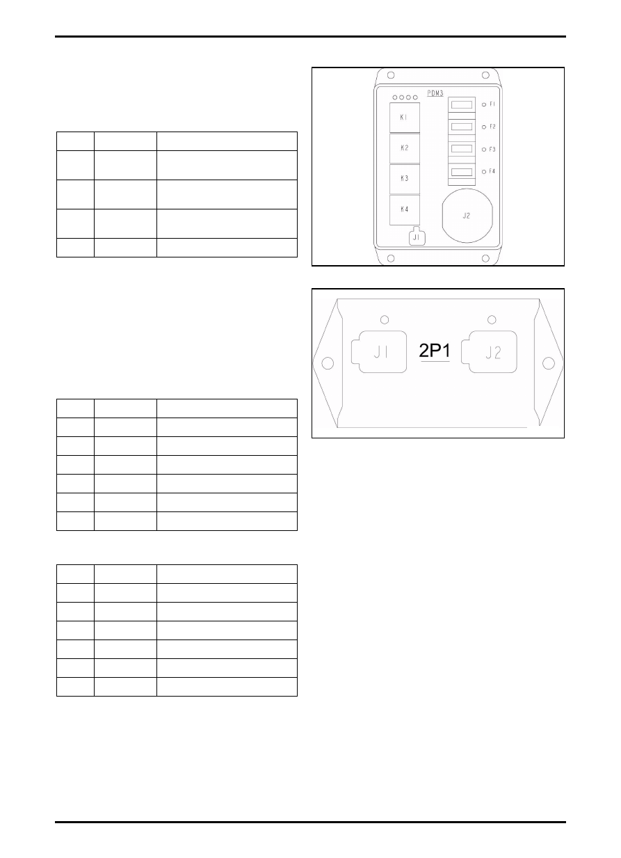
PDM3
FIG. 13: PDM3: High Current - Each circuit supplies
up to 30 amps.
PDM 3 has 4 relays which each supply power to 1 fuse;
meaning 4 fuses individually switched.
2-Pack Relay Modules
FIG. 14: 2-Pack Relay Modules (2P1 and 2P2)
2-Pack relay modules contain 2 independent
non-replaceable relays. Module housing contains 2
green LED’s to indicate which relay are on. Each output
can source a maximum of 15 amps. Relay pin out are
as follows:
J1 Connector
J2 Connector
Relay Module 2P1
A/C Compressor Clutch/Park Brake
Relay Module 2P2
Work Lights #3 (Optional)
FIG. 13
Q000078S
FUSE RATING
DESCRIPTION
F1
5A
ACCESSORY PLUG /
RADIO / GPS
F2
20A
WORK LIGHTS 3
(OPTIONAL)
F3
15A
HVAC PRESSURE
BLOWER
F4
25A
SEAT
FIG. 14
Q000070S
PIN
RELAY
FUNCTION
1
1
COIL INPUT
2
1
NOT USED
3
1
COIL OUTPUT
4
1
N.C. OUTPUT
5
1
N.O. OUPUT
6
1
COMMON INPUT
PIN
RELAY
FUNCTION
1
2
COIL INPUT
2
2
NOT USED
3
2
COIL OUTPUT
4
2
N.C. OUTPUT
5
2
N.O. OUPUT
6
2
COMMON INPUT