Challenger Terra Gator 3244 Chassis. Manual - part 25


  Index      Challenger     Challenger Terra Gator 3244 Chassis - service repair manual 2009 year


Search            


Content   ..  23  24  25  26   ..


Challenger Terra Gator 3244 Chassis. Manual - part 25


627333-A  

3-13

Transmission and Solenoids

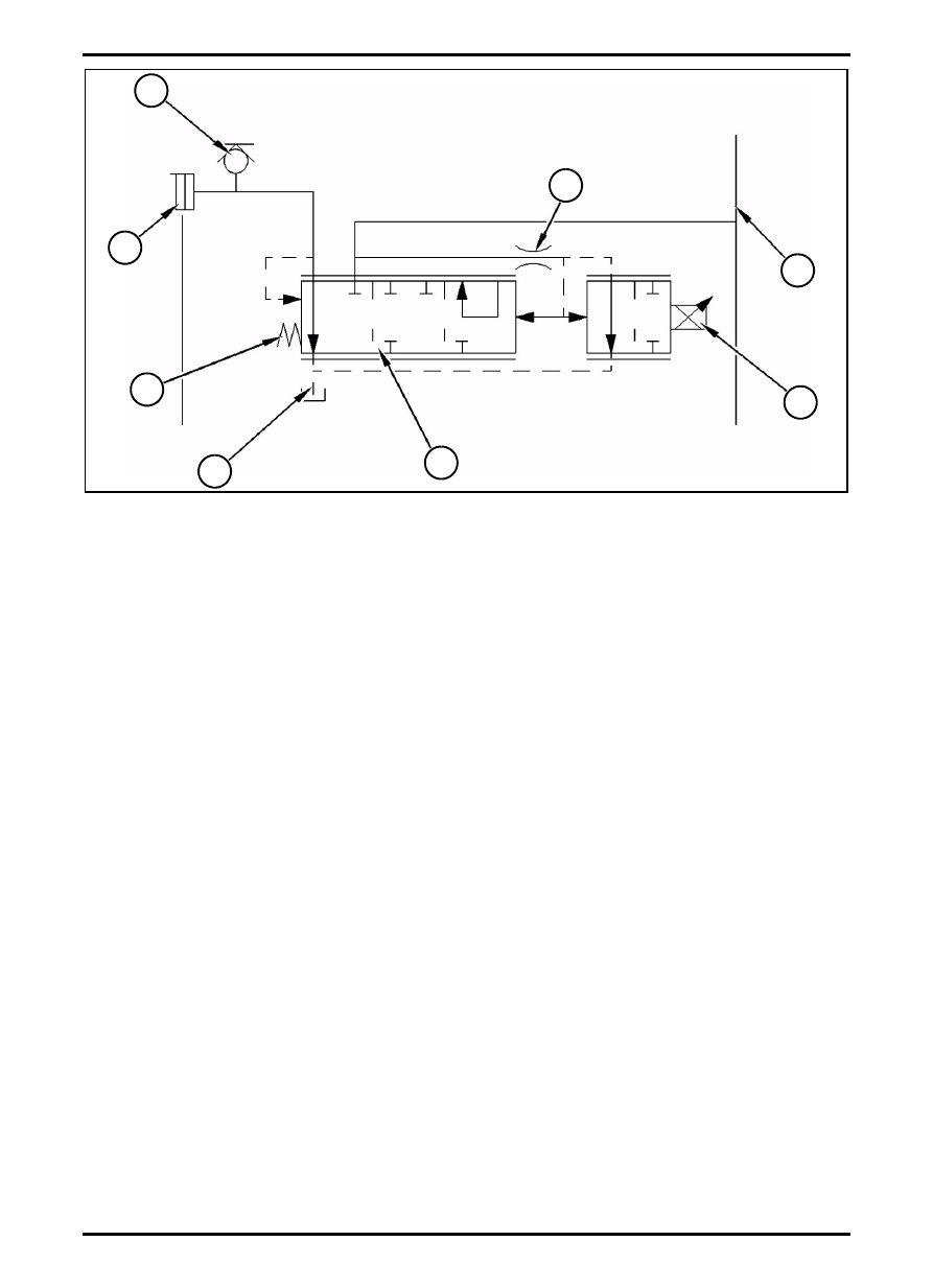
Schematic of modulating valve (transmission)

1. Modulating Valve (Transmission);

2. Test Port;

3. Transmission Clutch;

4. Spring;

5. Line to Sump;

6. Spool Orifice;

7. Charge Pressure Oil;

8. Solenoid.

Modulating valve (1) is controlled by transmission

electronic control module (ECM). The modulating valve

is used by the transmission ECM to directly modulate

the oil pressure that is sent to each of the nine

individual transmission clutches.

When the operator selects a direction or when the

operator selects a speed, the transmission ECM sends

a pulse width modulated signals in order to vary the

current to solenoid (8).

The distance that is travelled by the solenoid plunger is

proportional to the electrical current that is sent to the

solenoid. The position of the solenoid plunger controls

the oil pressure the is sent to transmission clutch (3).

When the transmission ECM sends the maximum

programmed current to the modulating valve, the

pressure in the transmission clutch will be at the

maximum desired pressure. When no current is sent to

the modulating valve, the oil pressure in the

transmission clutch will be zero.

FIG. 13

Q000038S

2

3

4

5

1

8

7

6

Transmission and Solenoids

3-14

627333-A  

Install/Remove Solenoids

Modulating Valve

Install Solenoids:

Always use new O-rings;

Lubricate the O-rings before installing;

Replace if needed a new valve.

Remove Solenoids:

Remove the electric connector;

Unscrew the two bolts on the solenoid;

Valve Port

FIG. 15: Bottom View of Modulating Valve

1. To Transmission Clutch;

2. Charge Pressure Oil;

3. To Transmission Clutch.

The figure shows the bottom view of the modulating

valve. The bottom view shows the porting for the inlet

and outlet flow of hydraulic oil.

Valve Operation

There are three basic stages of the controlled operation

of the modulating valve:

No Signal Current;

Partial Signal Current;

Maximum Signal Current.

FIG. 14

Q000043S

FIG. 15

Q000039S

1

2

3

627333-A  

3-15

Transmission and Solenoids

The operation of the modulating valve is not a simple

on/off cycle. The transmission ECM varies the strength

of the signal current through a programmed cycle in

order to control the movement of the proportional

solenoid valve spool.

3-16

627333-A  

Transmission and Solenoids

No Signal Current (Clutch Disengaged)

Modulating Valve

1. Modulating Valve;

2. Test Port;

3. To Transmission Clutch;

4. Spring;

5. Line to Sump;

6. Spool Orifice;

7. Charge Pressure Oil;

8. To Transmission Clutch;

9. Solenoid;

10. Ball;

11. Valve Spool;

12. Drain Orifice;

13. Pin;

14. Charge Pressure;

15. Sump.

The transmission ECM controls the rate of oil flow

through modulating valve (1) by changing the strength of

the signal current to solenoid (9). When signal current is

not being sent to the solenoid, the solenoid will be

de-energized.

Oil Flow in a De-energized Valve

Spring (1) holds the valve spool to the left in the valve

body.

The valve spool opens the passage between

transmission clutch (3) and the sump.

The valve spool blocks the passage between the

transmission clutch and the charge pressure oil.

Consequently, pressurized oil flow is blocked to the

transmission clutch.

Charge pressure oil (7) flows from the charge pump into

the valve body and around valve spool (11).

The oil flows through the drilled passage that is in the

valve spool and into spool orifice (6). The spool orifice in

on the left side of the valve spool. The oil then flows onto

drain orifice (12).

Because there is no force on pin (13), in order to hold

ball (10) against the drain orifice, the oil flows through

the valve spool. The oil flows through the drain orifice,

around the ball and to sump (5).

Oil from the transmission clutch will drain into the sump.

As a result, the transmission clutch in not engaged.

FIG. 16

Q000040S

8

11

12

5

3

7

4

13

1

2

6

10

14

15


Content   ..  23  24  25  26   ..