Yamaha XV1700P, XV1700PC. Service Manual - part 8
3 - 8
CHK
ADJ
AIR FILTER CASE
EAS00043
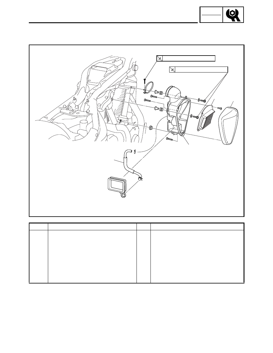
AIR FILTER CASE
4
1
3
2
(4)
T
R
.
.
7 Nm (0.7 m
•
kg, 5.1 ft
•
Ib)
T
R
.
.
3 Nm (0.3 m
•
kg, 2.2 ft
•
Ib)
Order
Job/Part
Q’ty
Remarks
Removing the air filter case
Remove the parts in the order listed.
Fuel tank
Refer to “FUEL TANK”.
1
Air filter case
1
2
Air filter case cover
1
3
Air filter element
1
4
Air filter check hose
1
For installation, reverse the removal
procedure.