Yamaha XVS1100 (L). Service Manual - part 21


  Index      Manuals     Yamaha XVS1100 (L). Service Manual


Search            copyright infringement  


Content      ..     19      20      21      22     ..


Yamaha XVS1100 (L). Service Manual - part 21


7-28

Y

G

Check the dimmer switch for continuity.
Refer to “CHECKING THE SWITCHES”.

Is the dimmer switch OK?

YES

The dimmer switch is
faulty. Replace the
left handlebar switch.

NO

5. Dimmer switch

EAS00786

Check the pass switch for continuity.
Refer to “CHECKING THE SWITCHES”.

Is the pass switch OK?

YES

The pass switch is
faulty. Replace the
left hadlebar switch.

NO

6. Pass switch

EAS00787

Check the entire lighting system’s wiring.
Refer to “CIRCUIT DIAGRAM”.

Is the lighting system’s wiring properly con-
nected and without defects?

YES

Properly connect or
repair the lighting sys-
tem’s wiring.

NO

7. Wiring

Check the condition
of each of the lighting
system’s circuits.
Refer to “CHECKING
THE LIGHTING SYS-
TEM”.

Check the headlight bulb and socket for con-
tinuity.
Refer to “CHECKING THE BULBS AND
BULB SOCKETS”.

Are the headlight bulb and socket OK?

YES

Replace the head-
light bulb, socket or
both.

NO

1. Headlight bulb and socket
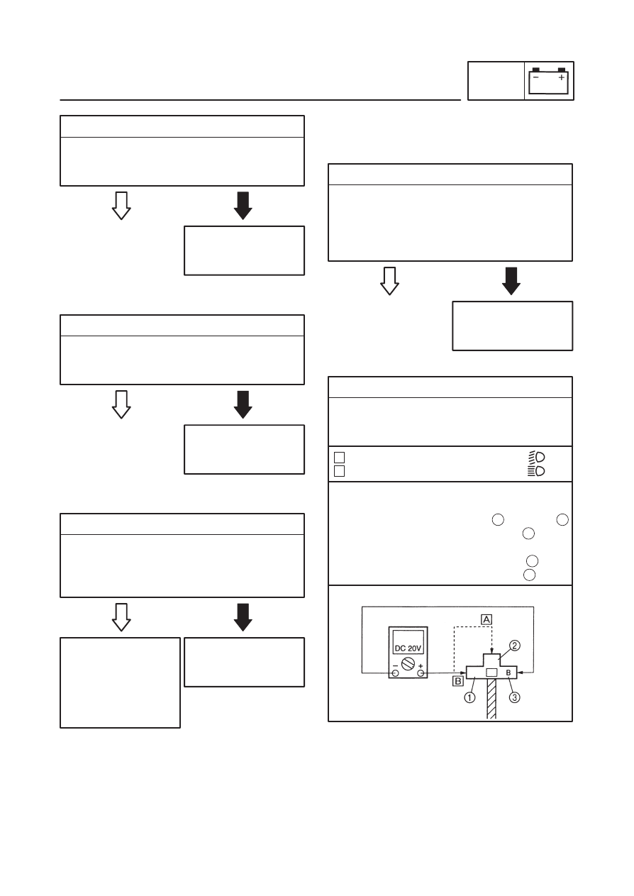
2. Voltage

Connect the pocket tester (DC 20 V) to the
headlight and high beam indicator light cou-
plers as shown.

When the dimmer switch is set to “

When the dimmer switch is set to “

A
B

Headlight coupler (wire harness side)

EAS00788

CHECKING THE LIGHTING SYSTEM
1. The headlight and the high beam indicator

light fail to came on.

Headlight

Tester positive probe 

yellow 

 or green 

Tester negative probe 

 black 

High beam indicator light

Tester positive probe 

 yellow 

Tester negative probe 

 brack

1

2

3

4

5

LIGHTING SYSTEM

ELEC

EAS00784

7-29

Set the main switch to “ON”.

Set the light switch to “    ”.

Set the dimmer switch to “     ” or “ 

”.

Measure the voltage (12 V) of yellow     or
green     on the headlight coupler (headlight
side).

Measure the voltage (12V) of yellow      on the
meter assembly coupler.

Is the voltage within specification?

2

YES

Replace the meter
light bulb, socket or
both.

NO

EAS00789

2. A meter light fails to come on.

1. Meter light bulb and socket.

Check the meter light bulb and socket for
continuity.
Refer to “CHECKING THE BULBS AND
BULB SOCKETS”.

Are the meter light bulb and socket OK?

The wiring circuit
from the main switch
to the headlight cou-
pler is faulty and must
be repaired.

NO

YES

2. Voltage

Connect the pocket tester (20 V) to the meter
assembly coupler (wire harness side) as
shown.

Tester positive probe 

 blue 

Tester negative probe 

 black

1

2

This circuit is OK.

Replace the tail /
brake lightbulb, sock-
et or both.

NO

YES

The wiring circuit
from the main switch
to the meter assem-
bly coupler is faulty
and must be re-
paired.

NO

This circuit is OK.

EAS00790

3. A tail / brake light fails to come on.

1. Tail / brake light bulb and socket

Check the tail / brake light bulb and socket for
continuity.
Refer to “CHECKING THE BULBS AND
BULB SOCKETS”.

Are the tail / brake light bulb and socket OK?

YES

Set the main switch to “ON”.

Set the light switch to “      

” or “

”.

Measure the voltage (12 V) of blue     on the
meter assembly coupler (wire harness side).

Is the voltage within specification?

1

B

1

4

LIGHTING SYSTEM

ELEC

7-30

2. Voltage

Connect the pocket tester (DC 20 V) to the
tail / brake light coupler (wire harness side) as
shown.

Tester positive probe 

 blue 

Tester negative probe 

 black

1

2

YES

The wiring circuit
from the main switch
to the tail / brake light
coupler is faulty and
must be repaired.

NO

This circuit is OK.

Set the main switch to “ON”

Set the light switch to “      

” or “

  ”.

Measure the voltage (12 V) of blue / red     on
the tail / brake light coupler (wire harness
side).

Is the voltage within specification?

1

Replace the auxiliary
light bulb, socket or
both.

NO

EB05413

4. The auxiliary light fails to come on. (for Eu-

rope)

1. Auxiliary light bulb and socket

Check the auxiliary light bulb and socket for
continuity.
Refer to “CHECKING THE BULBS AND
BULB SOCKETS”.

Are the auxiliary light bulb and socket OK?

YES

2. Voltage

Connect the pocket tester (DC 20 V) to the
auxiliary light couplers (wire harness side) as
shown.

Tester positive probe 

 blue / red 

Tester negative probe 

 black

1

2

YES

The wiring circuit
from the main switch
to the auxiliary light
connectors is faulty
and must be re-
paired.

NO

This circuit is OK.

Set the main switch to “ON”

Set the light switch to “   

  ” or “    ”.

Measure the voltage (12 V) of blue / red     on
the auxiliary light couplers (wire harness
side).

Is the voltage within specification?

1

LIGHTING SYSTEM

ELEC

7-31

SIGNAL SYSTEM

ELEC

EB806000

SIGNAL SYSTEM

CIRCUIT DIAGRAM

7-32

SIGNAL SYSTEM

ELEC

4 Main switch

6 Ignition fuse

7 Battery

8 Main fuse

11

Oil level gauge

12

Oil lamp relay

20

Neutral switch

22

Oil warning light

24

Turn signal indicator light

26

Neutral indicator light

30

Flasher relay

31

Turn signal switch

32

Rear turn signal light (R)

33

Rear turn signal light (L)

34

Front turn signal light (R)

35

Front turn signal light (L)

40

Front brake switch

42

Horn

43

Horn switch

45

Rear brake switch

50

Tail / brake light

53

Signal fuse

7-33

SIGNALING SYSTEM

ELEC

Open-circuit voltage

12.8 V or more at 20

_

C

YES

Replace the fuse(-s).

NO

YES

S

Clean the battery
terminals.

S

Recharge or re-
place the battery.

NO

Replace the main
switch.

NO

EAS00749

3. Main switch

S

Check the main switch for continuity.
Refer to “CHECKING THE SWITCHES”.

S

Is the main switch OK?

YES

1. Main, ignition and signaling system fuses

S

Check the main ignition and signaling sys-
tem fuses for continuity.
Refer to “CHECKING AND CHARGING
THE FUSES” in chapter 3.

S

Are the main ignition and signaling system
fuses OK?

2. Battery

S

Check the condition of the battery.
Refer to “CHECKING THE BATTERY” in
chapter 3.

S

Is the battery OK?

NO

EAS00795

4. Wiring

S

Check the entire signaling system’s wiring.
Refer to “CIRCUIT DIAGRAM”.

S

Is the signaling system’s wiring properly con-
nected and without defects?

YES

Properly connect or
repair the signaling
system’s wring.

Check the condition
of each of the signal-
ing system’s circuits.
Refer to “CHECKING
THE SIGNALING
SYSTEM”.

NOTE:

EB806010

EAS00739

TROUBLESHOOTING

S

Any of the following fail to light: turn sig-
nal light, brake light or an indicator light.

S

The forn fails to sound.

Check:
1. main and signaling system fuses
2. battery
3. main switch
4. wiring

(of the entrire signaling system)

S

Before troubleshooting, remove the following
part(-s):

1) battery cover
2) rider’s seat
3) fuel tank
4) steering head side covers
5) headlight lens unit
6) tool box cover
7) left side cover

S

Troubleshoot with the following special
tool(-s).

Pocket tester

90890-03112

EAS00738

7-34

SIGNALING SYSTEM

ELEC

Replace the left han-
dlebar switch.

NO

1. Horn switch

Check the forn switch for continuity.
Refer to “CHECKING THE SWITCHES”.

Is the horn switch OK?

YES

2. Voltage

Connect the pocket tester (DC 20 V) to the
horn connecter at the horn terminal as
shown.

Tester positive probe 

 brown 

Tester negative probe 

 ground

1

The horn is OK.

YES

3. Horn

Disconnect the black connector at the horn
terminal.

Connect a jumper lead 

 to the horn terminal

and ground the jumper lead.

Set the main switch to “ON”.

Does the horn sound?

NO

4. Voltage

Connect the pocket tester (DC 20 V) to the
horn connecter at the black terminal as
shown.

Tester positive probe 

 black 

Tester negative probe 

 ground

1

Set the main switch to “ON”.

Measure the voltage (12 V) of brown at the
horn terminal.

Is the voltage within specification?

The wiring circuit
from the main switch
to the horn connecter
is faulty and must be
repaired.

NO

YES

Set the main switch to “ON”.

Measure the voltage (12 V) of black     at the
horn terminal.

Is the voltage within specification?

1

NO

YES

Replace the horn.

Repair or replace the
horn.

1

Br

P

Br

Br

P

EAS00796

CHECKING THE SIGNALING SYSTEM
1. The horn fails to sound.

7-35

SIGNALING SYSTEM

ELEC

Replace the tail /
brake lightbulb, sock-
et or both.

NO

1. Tail / brake light bulb and socket

Check the tail / brake light bulb and socket for
continuity.
Refer to “CHECKING THE BULBS AND
BULB SOCKETS”.

Are the tail / brake light bulb and socket OK?

YES

3. Voltage

Connect the pocket tester (DC 20 V) to the
tail / brake light coupler (wire harness side) as
shown.

Tester positive probe 

 yellow 

Tester negative probe 

 black

1

Replace the brake
light switch.

NO

2. Brake light switches

Check the brake light switches for continuity.
Refer to “CHECKING THE SWITCHES”.

Is the brake light switch OK?

YES

2

YES

The wiring circuit
from the main switch
to the tail / brake light
coupler is faulty and
must bne repaired.

NO

This circuit is OK.

Set the main switch to “ON”.

Pull in the brake lever or push down on the
brake pedal.

Measure  the voltage (12 V) of yellow at the
tail / brake light coupler (wire harness side).

Is the voltage within specification?

Replace the turn sig-
nal light bulb, socket
or both.

NO

EAS00799

3. A turn signal light, turn signal indicator light

or both fail to blink.

1. Turn signal light bulb and socket

Check the turn signal light bulb and socket for
continuity.
Refer to “CHECKING THE BULBS AND
BULB SOCKETS”.

Are the turn signal light bulb and socket OK?

YES

EAS00797

2. A tail / brake light fails to come on.

7-36

Turn signal light
Turn signal indicator light

Replace the left han-
dlebar switch.

NO

2. Turn signal switch

Check the turn signal for continuity.
Refer to “CHECKING THE SWITCHES”.

Is the turn signal switch OK?

YES

The wiring circuit
from the main switch
to the flasher relay
coupler (flasher relay
side) is faulty and
must be repaired.

NO

3. Voltage

Connect the pocket tester (DC 20 V) to the
flasher relay coupler (wire harness side) as
shown.

YES

Tester positive prove 

 brown 

Tester negative prove 

 ground

1

Set the main switch to “ON”.

Measure the voltage (12 V) of brown      at the
flasher relay coupler (wire harness side).

Is the voltage within specification?

1

4. Voltage

Connect the tester (DC 20 V) to the flasher

relay coupler (wire harness side) as shown.

The flasher relay is
faulty and must be re-
placed.

NO

YES

1

Set the main switch to “ON”.

Set the turn signal switch to “    ” or “

  ”.

Measure the voltage (12 V) or brown / white at
the flasher relay coupler (wire harness side).

Is the voltage within specification?

Tester positive probe 

 brown / white 

Tester negative probe 

 ground

5. Voltage

Connect the pocket tester (DC 20 V) to the turn
signal light connectors or the meter assembly
coupler (wire harness side) as shown.

A
B

Left turn signal light

Tester positive probe 

 chocolate 

Tester negative probe 

 ground

Right turn signal light

Tester positive probe 

 daek green 

Tester negative probe 

 ground

1

2

R/W

R/W

A

B

SIGNALING SYSTEM

ELEC

7-37

Tester positive probe 

 brown 

Tester negative probe 

 sky blue

Replace the neutral
indicator light bulb,
socket or both.

NO

YES

The wiring circuit
from the turn signal
switch to the turn sig-
nal light connector is
faulty and must re-
paired.

NO

This circuit is OK.

EAS00800

4. The neutral indicator light fails to come on.

1. Neutral indicator light bulb and socket

Check the neutral indicator light bulb and
socket for continuity.
Refer to “CHECKING THE BULBS AND
BULB SOCKETS”.

Are the neutral indicator light bulb and socket
OK?

YES

Set the main switch to “ON”.

Set the turn signal switch to “

” or “

”.

Measure the voltage (12 V) of chocolate     or
dark green     at the turn signal light connec-
tor (wire harness side).

Is the voltage within specification?

1

2

Replace the neutral
switch.

NO

2. Neutral switch

Check the neutral switch for continuity.
Refer to “CHECKING THE SWITCHES”.

Is the neutral switch OK?

YES

3. Voltage

Connect the pockt tester (DC 20V) to the me-
ter assembly coupler (wire harness side) as
shwon.

1

2

YES

The wiring circuit
from the main switch
to the meter light
bulb coupler is faulty
and must be re-
paired.

NO

This circuit is OK.

Set the main switch to “ON”.

Measure the voltage (12 V) of brown 

 and

sky blue 

 at the meter assembly coupler.

Is the voltage with specification?

1

L / R

2

Replace the oil level
warning light bulb,
socket or both.

NO

EAS00802

5. The oil level warning light fails to come on.

1. Oil level warning light bulb and socket

Check the oil level warning light bulb and
socket for continuity.
Refer to “CHECKING THE BULBS AND
BULB SOCKETS”

Are the oil level warning light bulb and socket
OK?

YES

SIGNALING SYSTEM

ELEC

7-38

Set the main switch to “ON”.

Measure the voltage (12 V) of brown     and
black / red at the meter assembly coupler.

Is the voltage within specification?

Drain the engine oil and remove the oil level
switch from the oil pan.

Check the oil level switch for continuity.
Refer to “CHECKING THE SWITCHES”.

Is the oil level switch OK?

2. Oil level switch

YES

Replace the oil level
switch.

NO

3. Oil lamp relay

Disconnect the oil lamp relay from the coupler.

Connect the pocket tester (


 1) and bat-

tery (12 V) to the oil lamp relay terminals as
shown.

YES

Replace the oil lamp
relay.

NO

Battery positive terminal 

 red / white  

Battery negative terminal 

 black / red

1

2

Tester positive probe 

 black / white 

Tester negative probe 

 black

3

4

Does the oil lamp relay have continuity be-
tween red / blue and black?

4. Voltage

Connect the pocket tester (DC 20 V) to the
meter assembly coupler (wire harness side)
as shown.

Tester positive probe 

 red / white 

Tester negative probe 

 black / white

1

YES

The wiring circuit
from the main switch
to the meter assem-
bly coupler is faulty
and must be re-
paired.

NO

This circuit is OK.

1

2

SINGNAL SYSTEM

ELEC

7-39

FUEL PUMP SYSTEM

ELEC

4

6

7

8

13

14

16

38

Main switch

Ignition fuse

Battery

Main fuse

Starting circuit cutof

f relay

Fuel pump

Ignitor unit

Engine stop switch

EB808000

FUEL PUMP SYSTEM

CIRCUIT DIAGRAM

7-40

FUEL PUMP SYSTEM

ELEC

1

Battery

2

Main fuse

3

Main switch

4

Ignition fuse

5

Engine stop switch

6

Ignitor unit

7

Fuel pump relay

8

Fuel pump

EB808010

FUEL PUMP CIRCUIT OPERATION
The fuel pump circuit consists of the fuel pump
relay, fuel pump, engine stop switch and ignitor
unit.
The ignitor unit includes the control unit for the
fuel pump.

7-41

FUEL PUMP SYSTEM

ELEC

2. Battery

S

Check the condition of the battery.
Refer to “CHECKING AND CHARGING
THE BATTERY” in chapter 3.

Open-circuit voltage

12.8 V or more at 20

_

C

S

Is the battery OK?

YES

S

Clean the battery
terminals.

S

Recharge or repla-
ve the battery.

NO

EAS00749

S

Check the main switch for continuity.
Refer to “CHECKING THE SWITCHES”.

S

Is the main switch OK?

YES

Replace the main
switch.

NO

3. Main switch

EAS00750

S

Check the engine stop switch for continuity.
Refer to “CHECKING THE SWITCHES”.

S

Is the engine stop switch OK?

YES

Replace the right
handlebar switch.

NO

4. Engine stop switch

NOTE:

YES

NO

Replace the fuse(-s).

1. Main, and ignition fuses

S

Check the main, and ignition fuses for conti-
nuity.
Reger to “CHECKING THE FUSES” in
chapter 3.

S

Are the main, and ignition fuses OK?

EAS00781

EAS00739

TROUBLESHOOTING

The fuel pump fails to operate.

Check:
1. main, and ignition fuses
2. battery
3. main switch
4. engine stop switch
5. starting circuit cutoff relay (fuel pump relay)
6. fuel pump
7. wiring

(of the entire charging system)

S

Before troubleshooting, remove the following
part (-s):

1) battery cover
2) rider’s seat
3) fuel tank
4) tool box cover
5) left side cover

S

Troubleshoot with the following special tool
(-s).

Pocket tester

90890-03112

EAS00738

7-42

Tester (+) lead 

 Blue / Black terminal 

Tester (–) lead 

 Black terminal

YES

Replace the starting
circuit cutoff  relay.

NO

Battery (+) terminal 

Red / Black terminal 

Battery (–) terminal 

Blue / Red terminal

2

1

Tester (+) lead 

 Red / Black terminal  

Tester (–) lead 

 Blue / Black terminal

3

1

S

Does the fuel pump relay have continuity
batween red / black and blue / black?

5. Starting circuit cutoff relay (fuel pump relay)

S

Remove the relay unit from the wire har-
ness.

S

Connect the pocket tester  (


 1) and bat-

tery (12 V) to the relay unit terminals.

6. Fuel pump resistance

S

Disconnect the fuel pump coupler from the
wire harness.

S

Connect the pocket tester (


 1) to the fuel

pump coupler terminals.

Fuel pump resistance:

1.6 

X

 2.2 

 at 20

_

C (68

_

F)

S

Measure the fuel pump resistance.

S

Is the fuel pump OK?

YES

Replace the fuel 
pump.

NO

S

Check the entire fuel pump system’s wiring.
Refer to “CIRCUIT DIAGRAM”.

S

Is the fuel pump system’s wiring properly
connected and without defects?

NO

Replace the ignitor
unit.

YES

7. Wiring

Properly connect or
repair the fuel pump
system’s wiring.

2

1

FUEL PUMP SYSTEM

ELEC

EB803023

EB808021

7-43

FUEL PUMP SYSTEM

ELEC

WARNING

EB808030

FUEL PUMP TEST

Gasoline is extremely flammable and under
certain circumstances there can be a danger
of an explosion or combustion. Be extreme-
ly careful and note the following points:

Stop the engine before refuelling.

Do not smoke and keep away from open
flames, sparks, or any other source of fire.

Take care not to spill gasoline. If you do ac-
cidentally spill some, wipe it up immediate-
ly with dry rags.

If gasoline touches the engine when the en-
gine is still hot, there is a danger of com-
bustion. Make sure that the engine is com-
pletely cool before performing the
following test.

1. Check:

Fuel pump operation

a. Fill up the fuel tank.
b. Put the end of the fuel hose into an open con-

tainer.

c. Connect the battery (12 V) to the fuel pump

coupler terminals.

Battery (+) lead 

 Blue / black terminal 

1

Battery (–) lead 

 Black terminal 

2

d. If fuel flows out from the fuel hose, the fuel

pump is good. If not, replace the fuel pump
assembly.


Content      ..     19      20      21      22     ..