ATV Arctic Cat 2001 Line. Service Manual - part 13
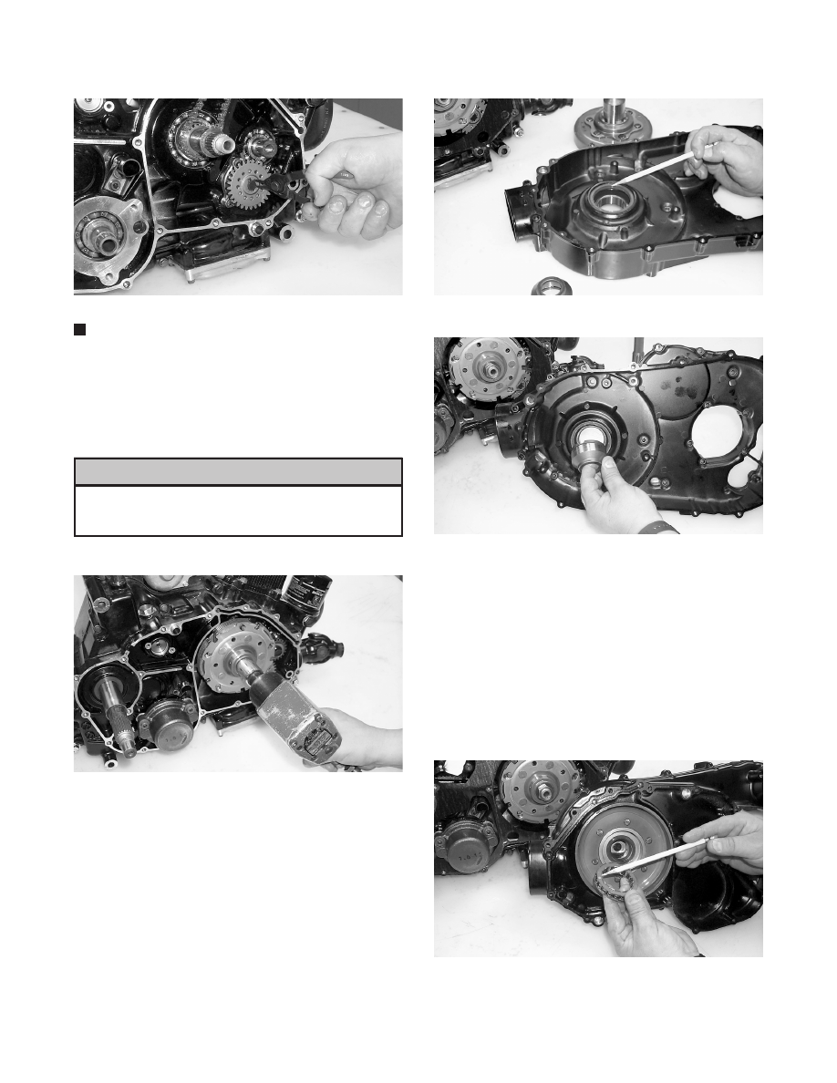
Fig. 3-694
CC609
NOTE: When installed correctly, the sides of the
drive and driven gears will be flush with each other.
6. Install the clutch shoe assembly and secure with the
washer (with the flat side facing the assembly as
noted in removing) and the nut (threads coated with
red Loctite #271). Tighten to 13 kg-m (94 ft-lb).
Care must be taken that the directional washer
be installed correctly and note that the nut has
left-hand threads.
Fig. 3-695
CC604
7. Lightly grease the clutch housing seal; then insert
the left fixed drive spacer.
Fig. 3-696
CC597
Fig. 3-697
CC595
8. Install the clutch cover alignment pins into the
crankcase, apply oil to the cover gasket, and install
the gasket onto the crankcase.
9. Apply grease to the outer edges of the clutch
housing; then from inside the clutch cover, install
the clutch housing into the cover using a rubber
mallet.
10. Install the one-way clutch onto the clutch shoe
assembly.
Fig. 3-698
CC592
! CAUTION
3-138