ATV Arctic Cat 2002. Service Manual - part 15


  Index      Manuals     ATV Arctic Cat 2002. Service Manual


Search            copyright infringement  


Content      ..     13      14      15      16     ..


ATV Arctic Cat 2002. Service Manual - part 15


88

3

Removing/Disassembling

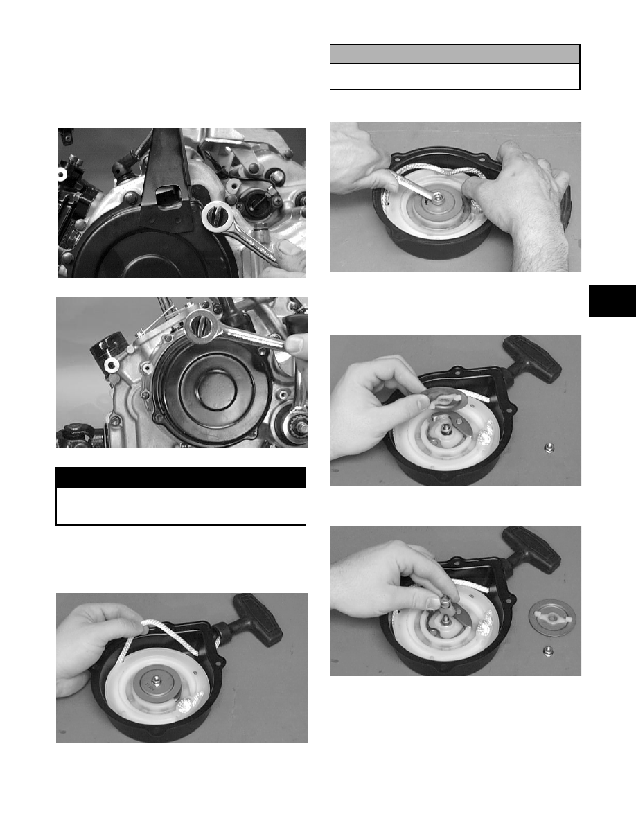
1. Remove the cap screws securing the recoil starter

assembly to the left-side cover; then remove the

starter noting (on the 250/300) the location of the

single washer closest to the center of the

crankcase. Account for a gasket.

4)

79)

2. Rotate the reel counterclockwise until the notch of

the reel is near the rope guide in the case. Guide

the rope into the notch and slowly allow the reel to

retract until all spiral spring tension is released.

>677)

3. Remove the nut.

>67)

4. Slowly release the friction plate and lift the plate

with ratchet guide free of the recoil housing; then

remove the ratchet guide from the friction plate.

>67)

5. Remove the spring, collar, and friction spring.

>67)

6. Remove the ratchet.

! WARNING

)   & ! 

! A

&;&$

! CAUTION

) &!

! $

RepairPro Service Manual

-------------------------------------------------------------------------------------------------------------------------------------------------------------

8?

>674)

7. Carefully lift the recoil free of the case making

sure the spring does not accidentally disengage

from the case.

>675)

8. Remove the protective cover from the starter

handle and pull the rope out of the handle; then

untie the knot in the rope and remove the handle.

„

  )  "  ! ! 

!&$, "&

!!"$,!

&!97$

9. Remove the spring from the housing by lifting the

spring end up and out. Hold the remainder of the

spring with thumbs and alternately release each

thumb to allow the spring to gradually release

from the housing.

10. Unwind the rope from the reel and remove the

rope.

Cleaning and Inspecting

„

  B"  !   A"&

&&!

&$

1. Clean all components.

2. Inspect the springs and ratchet for wear or

damage.

3. Inspect the reel and housing for cracks or damage.

4. Inspect the shaft for wear, cracks, or damage.

5. Inspect the rope for breaks or fraying.

6. Inspect the spiral spring for cracks, crystallization,

or abnormal bends.

7. Inspect the handle for damage, cracks, or

deterioration.

Assembling/Installing

1. If removed, insert the spring into the housing with

the outer end of the spring around the mounting

lug in the housing; then wind it in a

counterclockwise direction until the complete

spring is installed.

„

 !"&

$

>676)

2. Insert the rope through the hole in the reel and tie a

knot in the end; then wrap the rope counter-

clockwise around the reel leaving approximately

50 cm (20 in.) of rope free of the reel.

3. Apply low-temperature grease to the spring and

hub.

4. Thread the end of the rope through the guide hole

of the housing; then thread the rope through the

handle and secure it with a double knot. Install the

protective cover into the handle.

5. Align the inner hook of the spring with the notch

in the reel.

! WARNING


$B&";&$

-------------------------------------------------------------------------------------------------------------------------------------------------------------

89

3

>675)

6. Install the ratchet making sure the end is properly

installed on the reel.

>674)

7. Install the friction spring and the spring cover.

>67)

8. Install the friction plate with the ratchet guide

fitting into the ratchet.

>67)

9. While pushing down on the reel, install the nut.

Tighten securely.

>67)

10. With the 50 cm (20 in.) of rope exposed, hook the

rope in the notch of the reel.

11. Rotate the reel four turns counterclockwise; then

release the rope from the notch and allow the rope

to retract.

12. Pull the rope out two or three times to check for

correct tension.

„

  ,    !  

!$

13. Place the gasket and recoil starter assembly into

position on the left-side cover noting the location

of the single washer; then tighten the cap screws to

0.8 kg-m (6 ft-lb).

4)

RepairPro Service Manual

-------------------------------------------------------------------------------------------------------------------------------------------------------------

?7

79)

MEASURING SHIFT FORK 
(Thickness)

„

 B"

!&$

1. Using a calipers, in turn measure the thickness of

the machined tip of each shift fork.

96)

2. Shift fork thickness must be within the specified

range.

MEASURING SHIFT FORK GROOVE 
(Width)

1. Using a calipers, in turn measure the width of each

shift fork groove.

??)

2. Shift fork groove width must be within the

specified range.

MEASURING SHIFT FORK TO 
GROOVE (Side Clearance)

1. In turn, insert each shift fork into its groove.

2. Using a feeler gauge, measure the clearance

between the shift fork and the groove.

9)

3. Shift fork to groove side clearance must be within

specifications.

%.,//13.,3%%<57#77=

A&BAB ,A

& $&

, ; 

A& ,A

 $&

2%

7$&&

%.,//13.,3%%<477#577=

A& ,A

$&

, ; 

$&

2%

7$&7$&$

%.,//13*1'B,).<57#77=

A&BAB ,A

 &&7&

, ; A&

 ,A

&&$

2%

&&& &

%.,//13*1'B,).<477#577=

A& ,A


&

, ; 

&&

2%

&

&$&

$

&$&$

-------------------------------------------------------------------------------------------------------------------------------------------------------------

?

3

Servicing Right-Side 

Components

„


!!!#!!

 "$

„

  B"  !   A"&

&&

!&$

INSPECTING/MEASURING CLUTCH 
DRIVEN PLATE WARPAGE

„

 57#77"

 !

  $

444)

1. Inspect each driven plate for warpage and burn

marks.

2. In turn place each driven plate on the surface plate;

then using a feeler gauge, measure warpage in

several locations.

45)

3. Maximum driven plate warpage must be 0.1 mm

(0.004 in.).

MEASURING CLUTCH DRIVE 
PLATE (Fiber) THICKNESS

1. Using a calipers, in turn measure the thickness of

each drive plate in several locations.

4)

2. Drive plate thickness must be a minimum of 2.42

mm (0.094 in.) for the 250/300, a minimum of

2.62 mm (0.103 in.) for the 400, and within a

range of 2.92-3.08 mm (0.1149-0.1212 in.) for the

500.

3. If the fiber plate tabs are damaged, the plate must

be replaced.

4. Inspect the clutch hub (clutch sleeve hub on the

400/500) for grooves or notches. If grooves or

notches are present, replace the hub.

„

    57#77     

  &!!$

%.,//13*1'%,)(1

<57#77=

&

, ; 

2%

&

%.,//13*1'%,)(1

<477#577=

&

&

, ;  (

7

2%

 (

&

 (

7

RepairPro Service Manual

-------------------------------------------------------------------------------------------------------------------------------------------------------------

?

445)

INSPECTING STARTER CLUTCH 
SHOE

1. Inspect the starter clutch shoe for uneven wear,

chips, cracks, or burns.

2. Inspect the groove on the shoe for wear or

damage.

3. If any damage to the shoe or any groove wear is

noted, the shoe must be replaced.

'74

INSPECTING STARTER CLUTCH 
HOUSING

1. Inspect the starter clutch housing for burns, marks,

scuffs, cracks, scratches, or uneven wear.

2. If the housing is damaged in any way, the housing

must be replaced.

INSPECTING PRIMARY
ONE-WAY DRIVE

1. Insert the drive into the clutch housing.

2. Rotate the inner race by hand and verify the inner

race rotates only one direction.

3. If the inner race is locked in place or rotates both

directions, the drive assembly must be replaced.

MEASURING CLUTCH SPRING 
LENGTH

1. Using a calipers, measure the overall free length of

the clutch spring.

48)

2. Overall length must be a minimum of 27.5 mm

(1.08 in.) for the 250/300 and 33.7 mm (1.33 in.)

for the 400/500.

INSPECTING OIL PUMP

1. Inspect the pump for damage.

2. It is inadvisable to remove the screw securing the

pump halves. If the oil pump is damaged, it must

be replaced.

446)

MEASURING CAM CHAIN LENGTH 
(400/500)

1. Apply approximately 13 kg (28.5 lb) of force to

both ends of the cam chain.

2. With the chain extended, use a calipers to measure

the length along 20 pins.

-------------------------------------------------------------------------------------------------------------------------------------------------------------

?

3

'767

3. Standard length is 127.00-127.36 mm (4.99-

5.00 in.).

4. Maximum length must be 128.9 mm (5.07 in.).

Servicing Center 

Crankcase Components

„

  B"  !   A"&

&&

!&$

„


!!!J!!

 "$

SECONDARY GEARS

„

 B&

 "

$

Checking Backlash

„

       "    

"!$&

$

1. Place the left-side crankcase cover onto the

left-side crankcase half to prevent runout of the

secondary transmission output shaft.

2. Install the secondary driven output shaft assembly

onto the crankcase.

3. Mount the indicator tip of the dial indicator on the

secondary driven bevel gear.

4. While rocking the driven bevel gear back and

forth, note the maximum backlash reading on the

gauge.

5. Acceptable backlash range is 0.05-0.33 mm

(0.002-0.013 in.).

Correcting Backlash

„

  ,      

! &$

1. If backlash measurement is less than specified,

remove an existing shim, measure it, and install a

new thinner shim.

2. If backlash measurement is more than specified,

remove an existing shim, measure it, and install a

thicker shim.

„

 "

 $

$

Checking Tooth Contact

„


&" "&

$

1. Remove the secondary driven output shaft

assembly from the left-side crankcase half.

2. Clean the secondary driven bevel gear teeth of old

oil and grease residue.

3. Apply a thin, even coat of a machinist-layout dye

to several teeth of the gear.

4. Install the secondary driven output shaft assembly.

5. Rotate the secondary driven bevel gear several

revolutions in both directions.

6. Examine the tooth contact pattern in the dye and

compare the pattern to the illustrations.

'77

>-

%

C,

. )

)+

#

&

D2E",

1%&

0 )

)+

RepairPro Service Manual

-------------------------------------------------------------------------------------------------------------------------------------------------------------

?4

'775

'774

Correcting Tooth Contact

„

 ,!! 

!

&$

1. If tooth contact pattern is comparable to an

incorrect pattern, correct tooth contact according

to the following chart.

„

      !   

<=D>E 

 "D#%

E $

CRANKSHAFT ASSEMBLY

Measuring Connecting Rod 
(Small End Inside Diameter)

1. Insert a snap gauge into the upper connecting rod

small end bore; then remove the gauge and

measure it with micrometer.

97)

2. Maximum diameter is 17.040 mm (0.6709 in.) for

the 250/300, 21.04 mm (0.8283 in.) for the

375/400, and 23.04 mm (0.9070 in.) for the 500.

Measuring Connecting Rod 
(Small End Deflection)

1. Place the crankshaft on a set of V-blocks and

mount a dial indicator and base on the surface

plate. Position the indicator contact point against

the center of the connecting rod small end journal.

2. Zero the indicator and push the small end of the

connecting rod away from the dial indicator.

3. Maximum deflection is 3 mm (0.12 in.).

Measuring Connecting Rod
(Big End Side-to-Side)

1. Push the lower end of the connecting rod to one

side of the crankshaft journal.

2. Using a feeler gauge, measure the gap between the

connecting rod and crankshaft journal.

?9)

%


. ))+

  2

0 ))+

! CAUTION


      < &=$

    #

  !  &   

"$

-------------------------------------------------------------------------------------------------------------------------------------------------------------

?5

3

3. Acceptable gap range is 0.1-1.0 mm (0.004-0.039

in.).

Measuring Connecting Rod
(Big End Width)

1. Using a calipers, measure the width of the

connecting rod at the big-end bearing.

2. Acceptable width range is 17.95-18.00 mm

(0.707-0.709 in.) for the 250/300, 21.95-22.00 mm

(0.8642-0.8661 in.) for the 375, 25.95-26.00 mm

(1.022-1.024 in.) for the 400, and 24.95-25.00 mm

(0.9822-0.9842 in.) for the 500.

Measuring Crankshaft (Runout)

1. Place the crankshaft on a set of V blocks.

2. Mount a dial indicator and base on the surface

plate. Position the indicator contact at point 1 of

the crankshaft.

'784

3. Zero the indicator and rotate the crankshaft slowly.

4. Maximum runout is 0.05 mm (0.002 in.) for the

left side and 0.08 mm (0.003 in.) for the right side

on the 250/300, 0.05 mm (0.002 in.) for both sides

on the 400, and 0.08 mm (0.003 in.) for both sides

on the 375/500.

„

 2

 &!

!!4$

Measuring Crankshaft 
(Web-to-Web)

1. Using a calipers, measure the distance from the

outside edge of one web to the outside edge of the

other web.

'78

2. Acceptable width range is 54.9-55.1 mm

(2.161-2.169 in.) for the 250/300 and within a

range of 60.9-61.1 mm (2.398-2.406 in.) for the

375 and 70.9-71.1 mm (2.796-2.804 in.) for the

400/500.

DRIVESHAFT (Manual 
Transmission)

Disassembling

1. In order, remove the reverse dog, circlip, washer

(lock washer on the 250/300), reverse driven gear,

and bushing from the driveshaft.

?)

8)

! CAUTION

 !!

$

RepairPro Service Manual

-------------------------------------------------------------------------------------------------------------------------------------------------------------

?6

6)

5)

4)

„


"$

2. Remove the 1st driven washer (right side); then

remove the 1st driven gear from the driveshaft.

)

)

3. Remove the 1st driven bushing; then remove the

1st driven washer (left side) from the shoulder of

the splined shaft.

)

7)

„

 57#77"4"

!$

57?)

-------------------------------------------------------------------------------------------------------------------------------------------------------------

?8

3

4. Remove the 4th driven gear from the driveshaft.

Note the four small dogs facing toward the 3rd

driven gear for assembly purposes.

9)

5. Remove the 3rd driven circlip; then remove the

3rd driven washer (lock washer on the 250/300)

from the driveshaft.

6)

5)

6. Remove the 3rd driven gear from the driveshaft.

4)

7. Remove the 3rd driven bushing from the

driveshaft. Note the location of the oil feed hole in

the bushing and the matching oil supply hole in the

driveshaft for assembly purposes.

)

8. Remove the 3rd driven washer (lock washer on the

250/300) from the driveshaft. Note the tabs facing

toward the 5th driven gear for assembly purposes.

)

9. Remove the 3rd driven washer (lock washer on the

250/300) by rotating it out of the groove. Note the

groove closest to the 5th driven gear for assembly.

RepairPro Service Manual

-------------------------------------------------------------------------------------------------------------------------------------------------------------

??

)

10. Remove the 5th driven gear from the driveshaft.

7)

11. In order, remove the 2nd driven circlip, washer,

gear, and bushing from the driveshaft.

79)

7?)

78)

76)

 AT THIS POINT

 " &   %"

  !  

 $

-------------------------------------------------------------------------------------------------------------------------------------------------------------

?9

3

Assembling

8854>

84?

57#77

30

$ )"

$ )"*

$ )"*

4$ )"*

5$ )">

6$ 4)"*

8$ 5)"*

?$ 1")"*

9$ 1")

7$ 1")">

$ )"(B1

$ )"(B(

$ )"(B(

4$ )">

5$ )">

6$ )">

8$ )"!

?$ )"!

9$ )">1

7$ 1")"(B

$ )"(B(

$ )"B1

$ )"B

4$ 1")"!

5$ 4)"!

30

$ )"

$ )"*

$ )"*

4$ )"*

5$ )">

6$ 4)"*

8$ 5)"*

?$ 1")"*

9$ 1")

7$ 1")">

$ )"B1

$ )"B(

$ )"B(

4$ )">

5$ )">

6$ )">

8$ )"!

?$ )"!

9$ )">1

7$ 1")"B

$ )"B(
$ )"B1

$ )"B

4$ 1")"!

477#577

RepairPro Service Manual

-------------------------------------------------------------------------------------------------------------------------------------------------------------

97

1. In order, install the 2nd driven bushing, gear,

washer, and circlip onto the driveshaft.

76)

78)

7?)

79)

2. Install the 5th driven gear onto the driveshaft.

7)

3. Install the 3rd driven washer (lock washer on the

250/300). Lock it into the groove closest to the 5th

driven gear (as noted in disassembly) by rotating it

when it is in the groove.

)

4. Install the 3rd driven washer (lock washer on the

250/300) onto the driveshaft making sure the tabs

are facing toward the 5th driven gear. Make sure

the tabs intertwine with the 3rd driven washer on

the 400/500.

)

5. Install the 3rd driven bushing onto the driveshaft

making sure the oil feed hole in the bushing aligns

with the appropriate oil supply hole in the

driveshaft (as noted in disassembly).

-------------------------------------------------------------------------------------------------------------------------------------------------------------

9

3

)

6. In order, install the 3rd driven gear, washer (lock

washer on the 250/300), and circlip onto the

driveshaft.

4)

5)

6)

7. Install the 4th driven gear onto the driveshaft

making sure the four small dogs are facing toward

the 3rd driven gear as noted in disassembly.

9)

„

 57#77!$

57?)

8. Install the 1st driven washer onto the shoulder of

the splined shaft; then install the 1st driven

bushing and gear.

! CAUTION

,"&!

 !!&"

$,$

RepairPro Service Manual

-------------------------------------------------------------------------------------------------------------------------------------------------------------

9

7)

)

)

9. Install the washer on the shaft making sure it lines

up with the groove in the shaft; then turn the

washer locking it on the shaft.

)

10. Slide the reverse driven gear bushing onto the

shaft making sure the oil port in the bushing aligns

with the oil port on the shaft.

?4

11. Move the washer in the shaft groove until the

notches in the washer align with the tabs on the

bushing; then slide the bushing up tight against the

washer.

?4

12. In order, install the reverse driven gear, washer

(lock washer on the 250/300), circlip, and reverse

dog onto the driveshaft.

5)

! CAUTION

/!

$

-------------------------------------------------------------------------------------------------------------------------------------------------------------


Content      ..     13      14      15      16     ..