ATV Arctic Cat 2002. Service Manual - part 12
9
3
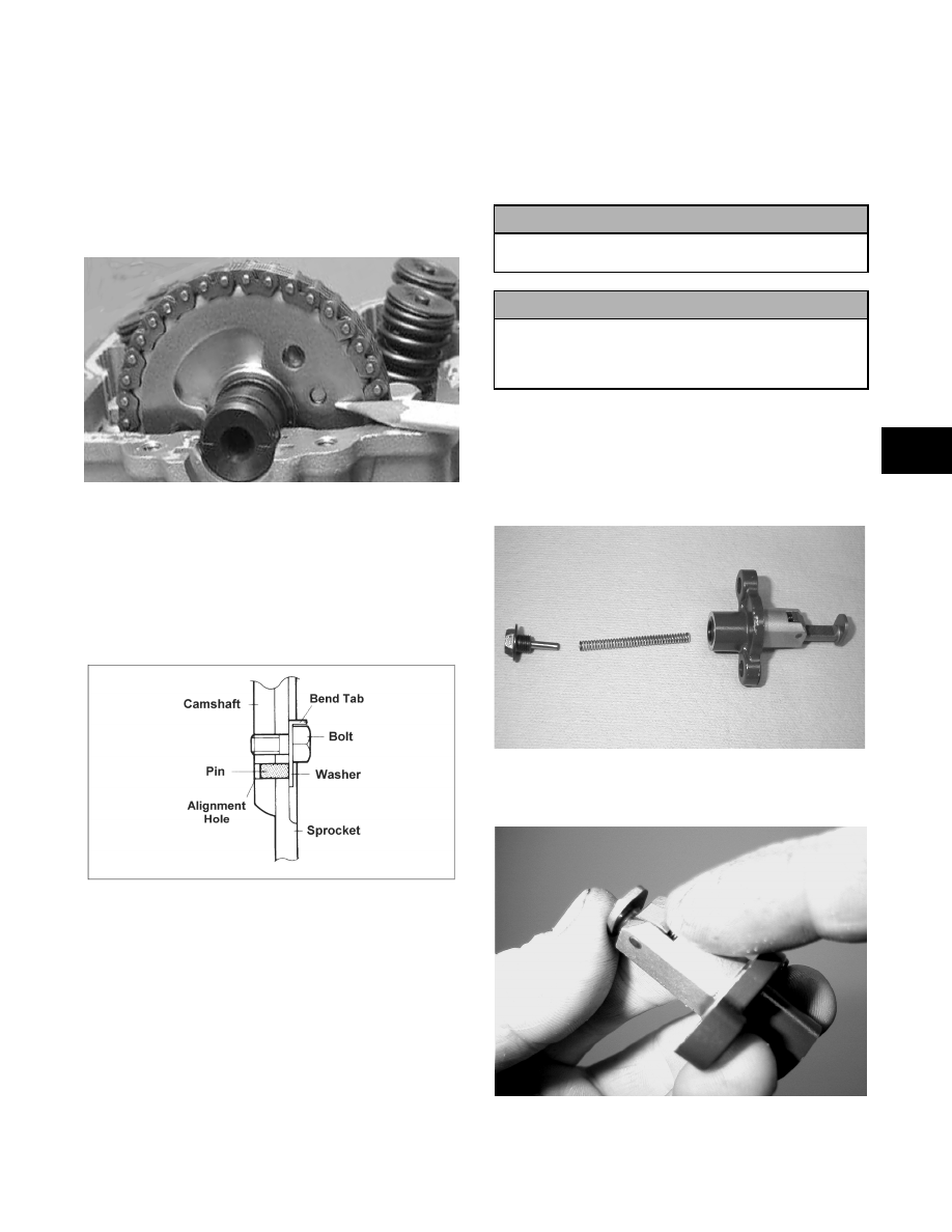
14. With the alignment pin installed in the camshaft
and the cam lobes directed down (toward the
piston), place the camshaft in position and verify
that the timing mark on the magneto is visible
through the inspection plug and that the timing
marks on the camshaft sprocket are parallel with
the valve cover mating surface.
B &
!
!$
-)6
15. Apply red Loctite #271 to the cap screws; then
install the cap screws and tab washer to the
camshaft sprocket. Tighten cap screws to 1.5 kg-m
(11 ft-lb).
2 !
"!
$
-)6
!
$& !
"""$,
&
!
!!$
16. When the camshaft assembly is seated, ensure the
following.
A. Piston still at top-dead-center.
B. Camshaft lobes directed down (toward the
piston).
C. Camshaft alignment marks parallel to the valve
cover mating surface.
D. Recessed side of the sprocket directed toward
the cam lobes.
E. Camshaft alignment pin and sprocket
alignment hole (smallest) are aligned.
17. Install the cylinder head plug with the open end
facing the camshaft.
18. Remove the cap screw from the end of the chain
tensioner. Account for the plunger, spring, and
O-ring.
-)4?
19. Depress the spring-loaded lock and push the
plunger into the tensioner.
-)46
! CAUTION
,& "
!&!$
! CAUTION
&"
!$ , !
"$
RepairPro Service Manual