ATV Arctic Cat 2002. Service Manual - part 6


  Index      Manuals     ATV Arctic Cat 2002. Service Manual


Search            copyright infringement  


Content      ..     4      5      6      7     ..


ATV Arctic Cat 2002. Service Manual - part 6


3

459)

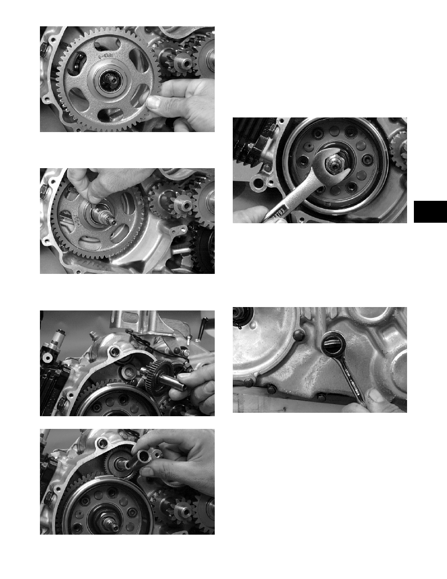
15. Place the magneto rotor into position on the

crankshaft making sure the key is in place.

45?)

16. Install the starter idler gear and shaft; then install

the spacer.

455)

454)

C. Stator Assembly/Cover
D. Starter Cup
E. Recoil Starter

„

  %! 6   !  

!!$

17. Install the magneto rotor nut on the crankshaft and

tighten until the rotor is properly seated; then

tighten to 16 kg-m (116 ft-lb).

46)

18. Place the gasket and left-side cover into position

on the crankcase making sure the alignment pins

are in place.

19. Install the cap screws to secure the left-side cover

noting the location of the different-sized cap

screws; then tighten to 0.9-1.3 kg-m (6.5-9.5

ft-lb).

44)

20. Place the starter cup into position on the

crankshaft making sure a new, lubricated O-ring is

inside the cup. Tighten the nut with lock washer to

3.5 kg-m (25 ft-lb).

RepairPro Service Manual

-------------------------------------------------------------------------------------------------------------------------------------------------------------

4

4)

21. Place the gasket and recoil starter assembly into

position on the left-side cover noting the location

of the single washer; then tighten the cap screws to

0.8 kg-m (6 ft-lb).

4)

Installing Top-Side 

Components

A. Piston
B. Cylinder

78844

„

 ,!"

C$

A. Install a thin oil ring, corrugated oil ring, and

thin oil ring in the bottom groove of the piston. 

477)

'7?5

B. Stagger the gaps of the upper and lower thin

rings.

„

  &

$

'74

F77&

30

$ &

$ %>

$ %>

4$ %>

5$ %>

6$ 

8$ &*

?$ 2

9$ 1F

! CAUTION

,!!

!

!$

! CAUTION

,    !  

$

-------------------------------------------------------------------------------------------------------------------------------------------------------------

5

3

1. Install the piston on the connecting rod making

sure there is a circlip on each side and the open

end of the circlip faces upwards.

„

   !      

!$

?)

?)

2. Place the two alignment pins into position. Place

the cylinder gasket into position; then place a

piston holder (or suitable substitute) beneath the

piston skirt and square the piston in respect to the

crankcase.

?)

3. Lubricate the inside wall of the cylinder; then

using a ring compressor or the fingers, compress

the rings and slide the cylinder over the piston.

Route the cam chain up through the cylinder cam

chain housing; then remove the piston holder and

seat the cylinder firmly on the crankcase.

55)

 4. Loosely install the two nuts which secure the

cylinder to the crankcase.

„

    &  

 !7$

?7)

! CAUTION

&&$)

 &     ! 

& &&$

RepairPro Service Manual

-------------------------------------------------------------------------------------------------------------------------------------------------------------

6

C. Cylinder Head
D. Valve Cover

7884

„

  %! 4   !  

!!$

5. Place the chain guide into the cylinder.

89)

6. On the 300, install the O-ring onto the front

left-side stud.

?4)

7. Place the head gasket into position on the cylinder.

Place the alignment pins into position; then place

the head assembly into position on the cylinder

making sure the chain is routed through the chain

cavity.

8?)

30

$ &.&

$ '"*

$ 1

4$ 2

5$ !%

6$ !%

8$ &.*

?$ 2

9$ *

7$ 

$ *

$ %>

4$ %!2

5$ ,!!

6$ 1

8$ &.2

?$ ,2!&

9$ 1

7$ !%

$ !

$ *

! CAUTION


 $

-------------------------------------------------------------------------------------------------------------------------------------------------------------

8

3

8. Install the three cylinder head cap nuts and one nut

with copper washers (note the locations of the cap

nuts and nut). Tighten only until snug.

88)

9. Loosely install the remaining cylinder head nuts.

86)

10. In a crisscross pattern, tighten the three cylinder

head cap nuts and one nut to 2.5 kg-m (18 ft-lb).

Tighten the remaining head nuts and the

cylinder-to-crankcase nuts to 1.1 kg-m (8 ft-lb).

11. Place the C-ring into position in its groove in the

cylinder head.

84)

12. Install the chain tensioner pad into the cylinder

head.

85)

„

    !     

 ;

&$

13. With the alignment pin installed in the camshaft

and the cam lobes directed down (toward the

piston), place the camshaft in its seating position;

then loop the chain over the sprocket and install

the sprocket onto the camshaft.

8)

„

 !

$& !

"""$,

&

 !!$

47)

„

  B    &  

!

!$

RepairPro Service Manual

-------------------------------------------------------------------------------------------------------------------------------------------------------------

?

47)

14. When the camshaft assembly is seated, ensure the

following.

A. Piston still at top-dead-center.

B. Camshaft lobes directed down (toward the

piston).

C. Camshaft alignment marks parallel to the valve

cover mating surface.

D. Recessed side of the sprocket directed toward

the cam lobes.

E. Camshaft alignment pin and sprocket

alignment hole (smallest) are aligned.

15. Place the tab washer onto the sprocket making

sure it covers the pin in the alignment hole.

'78

47)

16. Install the first cap screw securing the sprocket

and tab washer to the camshaft. Tighten only until

snug.

474)

17. Install the cylinder head plug in the cylinder head.

18. Remove the cap screw from the end of the chain

tensioner. Account for the plunger, spring, and

O-ring.

475)

19. Depress the spring-loaded lock and push the

plunger into the tensioner.

! CAUTION

,& "

 !&!$

! CAUTION


&"

 !$ ,   !  

"$

-------------------------------------------------------------------------------------------------------------------------------------------------------------

9

3

476)

20. Place the chain tensioner assembly and gasket into

the cylinder making sure the ratchet side is facing

toward the top of the cylinder and secure with the

two Allen-head cap screws.

87)

21. Install the cap screw into the end of the chain

tensioner.

69)

22. Rotate the crankshaft until the second cap screw

securing the sprocket to the camshaft can be

installed; then install the cap screw and tighten to

1.15 kg-m (8.5 ft-lb). Bend the tab to secure the

cap screw.

23. Rotate the crankshaft until the first cap screw

securing the sprocket to the camshaft can be

addressed; then tighten to 1.15 kg-m (8.5 ft-lb).

Bend the tab to secure the cap screw.

24. Loosen the adjuster screw jam nuts; then loosen

the adjuster screws on the rocker arms in the valve

cover.

478)

25. Apply a thin coat of Three Bond Sealant (p/n

0636-070) to the mating surface of the valve

cover.

47?)

26. Place the valve cover into position.

„

    !    

;"!$

27. Install the top side valve cover cap screws into the

head noting the locations of any with rubber

washers; then install the remaining cap screws.

Tighten only until snug.

68)

28. In a crisscross pattern starting from the center and

working outward, tighten the cap screws to 1 kg-m

(7 ft-lb).

RepairPro Service Manual

-------------------------------------------------------------------------------------------------------------------------------------------------------------

47

29. Adjust valve/tappet clearance using the following

procedure.

„

 +'"*!;<!#744479=

!$

A. Turn the engine over until the piston reaches

top dead center on the compression stroke.

B. Place the valve adjuster onto the jam nut

securing the tappet adjuster screw; then rotate

the valve adjuster dial clockwise until the end is

seated in the tappet adjuster screw.

C. While holding the valve adjuster dial in place,

use the valve adjuster handle and loosen the

jam nut; then rotate the tappet adjuster screw

clockwise until friction is felt.

5)

D. Align the valve adjuster handle with one of the

marks on the valve adjuster dial.

E. While holding the valve adjuster handle in

place, rotate the valve adjuster dial

counterclockwise until proper valve/tappet

clearance is attained.

„

  1   !!! %!

!!""#!!$

„

 1"";

!""#!! &

7$75<7$77$=!$

F. While holding the adjuster dial at the proper

clearance setting, tighten the jam nut securely

with the valve adjuster handle.

30. Place the two tappet covers with O-rings into

position; then tighten the covers securely.

66)

31. Install the spark plug and tighten to 1.7 kg-m

(12 ft-lb); then install the timing inspection plug.

4)

Installing 

Engine/Transmission

„


 ""

'$

1. Install the engine into the sub-frame assembly.

2. Connect each drive axle to the engine output

shafts.

3. Secure the upper A-arms with cap screws. Tighten

to 4.8 kg-m (35 ft-lb).

-------------------------------------------------------------------------------------------------------------------------------------------------------------

4

3

.788)

4. Secure the rear of the engine to the sub-frame with

cap screws and flat washers. Tighten to 5.5 kg-m

(40 ft-lb).

„

  A

!$

.785)

5. Secure the upper shock mount to the sub-frame.

Tighten to 4.8 kg-m (35 ft-lb).

.786)

6. Secure the front of the engine to the sub-frame

using a cap screw and spacers. Tighten to 5.5 kg-m

(40 ft-lb).

.784)

7. Secure the rear wheels to the hubs. Tighten to 5.5

kg-m (40 ft-lb).

8. Place the engine/sub-frame assembly onto a large

floor/transmission jack and place the sub-frame

assembly up and into position; then loosely start

all six mounting cap screws.

9. Tighten the four upper sub-frame mounting cap

screws in a crisscross pattern to 5.5 kg-m (40

ft-lb).

10. Tighten the two lower sub-frame mounting cap

screws to 5.5 kg-m (40 ft-lb).

11. Secure the skid plate to the rear end assembly.

Tighten securely.

12. Secure the two oil cooler hoses to the engine.

.787)

13. Secure the brake hose holder to the upper

suspension arm with a torx-head screw. Tighten

securely.

14. Tighten the rear hydraulic brake caliper to 2.8

kg-m (20 ft-lb).

! WARNING

%!!':

  #   &  

    "  ;&  

&$

RepairPro Service Manual

-------------------------------------------------------------------------------------------------------------------------------------------------------------

4

.76?)

15. Tighten the mechanical foot brake caliper to 2.1

kg-m (15 ft-lb).

16. Secure the oil light switch to its connector.

.768)

17. Secure the right-hand side panel.

.766)

18. Secure the remaining connectors to the main

wiring harness.

.765)

19. Install the air-cleaner assembly into the frame and

connect the crankcase breather hoses; then secure

the air-cleaner assembly to the frame. Tighten

securely.

.74?)

.748)

20. Secure the CDI unit to the frame. Tighten securely.

/??)

-------------------------------------------------------------------------------------------------------------------------------------------------------------

4

3

21. Install the carburetor into the air-intake boots; then

tighten the clamps. Route the vent hoses in the seat

stop holes.

.74)

22. Secure the air-intake snorkel to the air-cleaner

assembly and frame.

23. Secure the reverse gear shaft arm to the reverse

shift shaft making sure that the alignment marks

made during removing align. Tighten securely.

/94

24. Secure the shifter arm to the shifter arm shaft

making sure that the alignment marks made during

removing align. Tighten securely.

.767)

25. Secure the hi/lo shifter arm to the shifter arm shaft

making sure that the alignment marks made during

removing align. Tighten securely.

.75?)

26. Place the exhaust header pipe up to the engine

with the existing grafoil gaskets and springs.

.755)

27. Secure the muffler and exhaust pipe. Tighten

securely.

.756)

28. Turn the gas tank valve to the ON position.

29. Fill the engine with the correct motor oil (viscosity

and quantity).

RepairPro Service Manual

-------------------------------------------------------------------------------------------------------------------------------------------------------------

44

884

30. Install the battery and the battery hold-down

bracket.

31. Connect the positive cable to the battery first; then

the negative cable.

32. Install the seat.

33. Adjust the mechanical foot brake to within

specifications.

34. Remove the tie-down straps; then remove the ATV

from the support stand.

Table of Contents

(400/500 - Manual Transmission)

2%  

2%,  

4,  

2%4,(  

2%4,  

2),   

2%2),  

 +   

   + 3 %  

.  + 3     

# + 3    7

9 + 3 % 

0 2), 

0 4,(  

0 4,  7

0 ,  7 

0   $

Removing Engine/ 

Transmission

Many service procedures can be performed without

removing the engine/transmission from the frame.

Closely observe the note introducing each sub-section

for this important information.

Secure the ATV on a support stand to elevate the

wheels.

1. Remove the seat.

2. Remove the battery by removing the negative

cable first and then the positive cable.

! CAUTION

,;"&;

!  ! !!   

! <%=$,

 !!    !  

"&$

 AT THIS POINT

,: ;""#!

"<=!;

<=!;<=#

  <    #

=#

" "$

! WARNING

-   '  & !!  

!!";&$

! CAUTION

>& &

 $      "

 &$

-------------------------------------------------------------------------------------------------------------------------------------------------------------

45

3

3. Drain the oil from beneath the engine/

transmission; then drain the cooling system.

'779

4. Remove the gas tank (see Section 4).

5. Remove the front fenders and the front rack (see

Section 8).

6. Remove the two cap screws securing the exhaust

header pipe to the engine; then free the pipe from

the engine. Account for a grafoil gasket.

7. Loosen the exhaust pipe from the muffler at the

juncture in front of the muffler; then remove the

exhaust pipe.

/885)

8. Remove the cap screws securing the fender

extensions to the footrests; then remove the

footrests.

9. Mark the reverse gear shaft arm to the reverse shift

shaft to aid in assembly and remove the cap screw

securing the reverse gear shaft arm to the reverse

shift shaft; then remove the lock nut securing the

upper shift rod end to the shift lever arm. Remove

the shift rod.

/94

10. Detach the speedometer cable by loosening the

knurled nut and routing the cable away from the

engine/transmission.

/668)

11. Remove the four cap screws securing the rear

output joint to the transmission and push the shaft

away from the transmission.

9)

12. On 4x4 models, remove the cap screws and nuts

securing the propeller shaft to the front differential

coupler.

13. Detach the carburetor using the following

procedure.

A. Loosen the clamps securing the carburetor boot

and the air inlet boot.

RepairPro Service Manual

-------------------------------------------------------------------------------------------------------------------------------------------------------------

46

7)

„

 , &

 $

B. Route the carburetor assembly up and away

from the engine.

„

 + !

  & " !

"!$

14. Remove the clamp securing the upper coolant hose

to the thermostat housing; then disconnect the

hose.

5)

15. Disconnect the high tension lead from the spark

plug.

16. Disconnect the battery ground (negative) cable

from the crankcase cover; then disconnect the

positive cable from the starter motor.

1677)

1674)

17. Remove the clamp securing the lower coolant hose

to the water pump housing; then disconnect the

hose.

4)

18. Loosen the clamp on the crankcase breather vent

hose; then disconnect the hose and route it away

from the engine.

)

19. Remove the engine/transmission mounting

fasteners in the following sequence:

A. Upper front: Two cap screws (inside the

bracket) and one cap screw and nut (topside of

the engine).

-------------------------------------------------------------------------------------------------------------------------------------------------------------

48

3

/99

B. Lower front: One cap screw, nut, spacer, and

washer.

)

C. Upper rear: One cap screw and nut with flat

washer; then two left-side engine mount-to-

frame cap screws.

5)

D. Lower rear: One cap screw and nut with flat

washer.

6)

20. Remove the engine/transmission from the left side

of the frame.

Top-Side Components

„

 /& !  "

 &!

 "&

!$

;$

„

   #   "

"!$

Removing Top-Side 

Components

A. Valve Cover
B. Cylinder Head

„

  1"  ! !  

!!@

!

!$

1. Remove the two tappet covers.

 AT THIS POINT

 " &  ! ! &

  &  ! &  

&$.,%2,

 $

RepairPro Service Manual

-------------------------------------------------------------------------------------------------------------------------------------------------------------

4?

77)

„

  3!     

" &!!

 !!$

2. Remove the 12 cap screws securing the valve

cover to the head; account for the four rubber

washers on the top side cap screws. Remove the

valve cover. Account for and note the orientation

of the cylinder head plug. Note the location of two

alignment pins.

77)

84)

8)

3. Loosen the cap screw on the end of the tensioner;

then remove the two Allen-head cap screws

securing the tensioner adjuster assembly and

remove the assembly. Account for a gasket.

779)

77)

7)

-------------------------------------------------------------------------------------------------------------------------------------------------------------


Content      ..     4      5      6      7     ..