Suzuki GSX-R1000. Service Manual - part 5


  Index      Manuals     Suzuki GSX-R1000. Service Manual


Search            copyright infringement  


Content      ..     3      4      5      6     ..


Suzuki GSX-R1000. Service Manual - part 5


1A-2 Engine General Information and Diagnosis: 

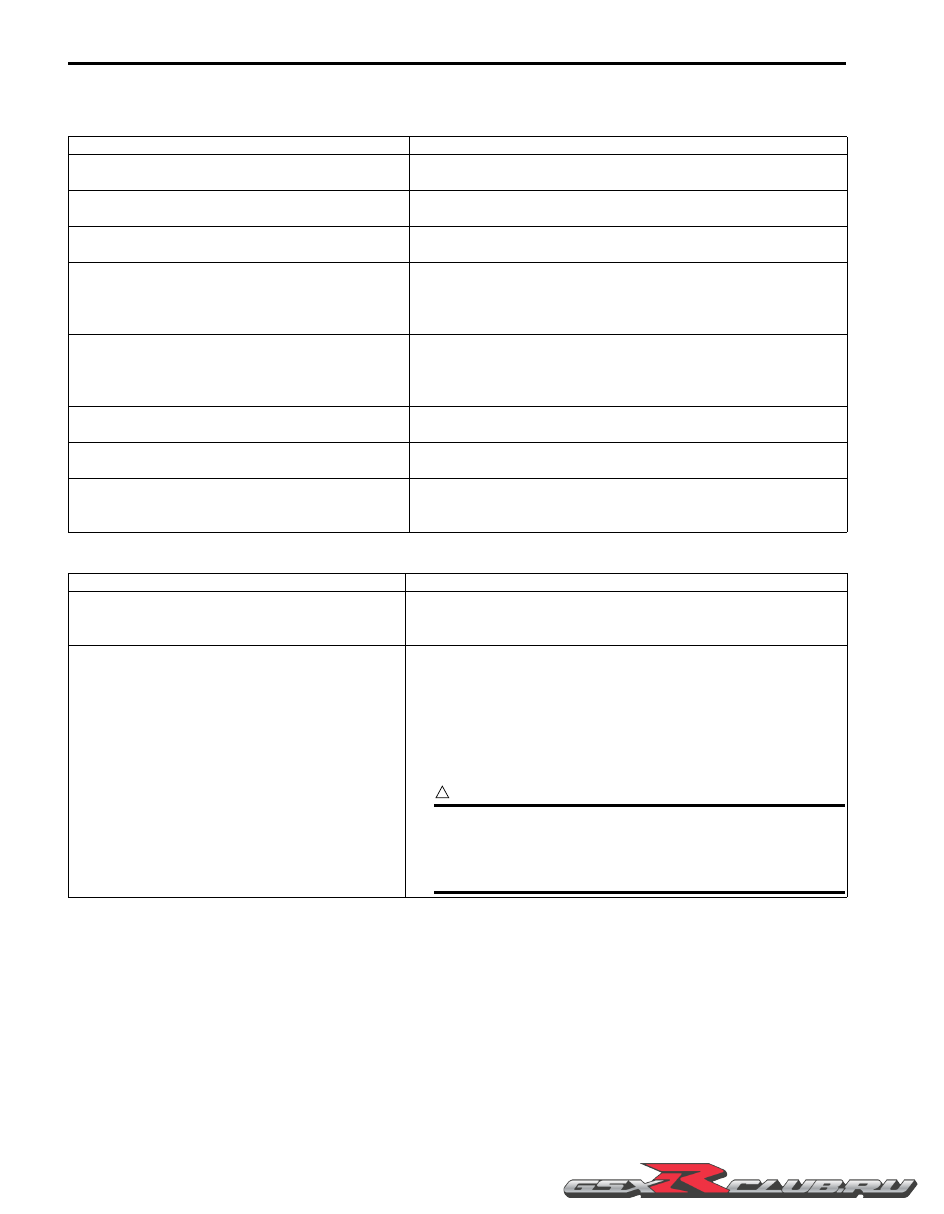
Compensation of Injection Time (Volume)

The following different signals are output from the respective sensors for compensation of the fuel injection time 
(volume).

Injection Stop Control

Signal

Descriptions

ATMOSPHERIC PRESSURE SENSOR SIGNAL

When atmospheric pressure is low, the sensor sends the signal to 
the ECM and reduce the injection time (volume).

ENGINE COOLANT TEMPERATURE SENSOR 
SIGNAL

When engine coolant temperature is low, injection time (volume) 
is increased.

INTAKE AIR TEMPERATURE SENSOR SIGNAL

When intake air temperature is low, injection time (volume) is 
increased.

HEATED OXYGEN SENSOR SIGNAL

Air/fuel ratio is compensated to the theoretical ratio from density 
of oxygen in exhaust gas. The compensation occurs in such a 
way that more fuel is supplied if detected air/fuel ratio is lean and 
less fuel is supplied if it is rich.

BATTERY VOLTAGE SIGNAL

ECM operates on the battery voltage and at the same time, it 
monitors the voltage signal for compensation of the fuel injection 
time (volume). A longer injection time is needed to adjust injection 
volume in the case of low voltage.

ENGINE RPM SIGNAL

At high speed, the injection time (volume) is increased. This is the 
compensation of the SRAD.

STARTING SIGNAL

When starting engine, additional fuel is injected during cranking 
engine.

ACCELERATION SIGNAL/DECELERATION 
SIGNAL

During acceleration, the fuel injection time (volume) is increased, 
in accordance with the throttle opening speed and engine rpm. 
During deceleration, the fuel injection time (volume) is decreased.

Signal

Descriptions

TIP-OVER SENSOR SIGNAL (FUEL SHUT-OFF)

When the motorcycle tips over, the tip-over sensor sends a signal 
to the ECM. Then, this signal cuts OFF current supplied to the fuel 
pump, fuel injectors and ignition coils.

OVER-REV. LIMITER SIGNAL

The fuel injectors stop operation when engine rpm reaches rev. 
limit rpm.
The fuel cut-off circuit is incorporated in this ECM in order to 
prevent over-running of engine. When engine speed reaches 13 
500 r/min, this circuit cuts off fuel at the fuel injectors. But under no 
load, the clutch lever is pulled or the gear position is in neutral, this 
circuit cuts off fuel when engine speed reaches 13 100 r/min.

CAUTION

!


Under no load, the engine can run over 13 100 r/min 
through the fuel cut-off circuit is effective, which may 
possibly cause engine damage. Do not run the engine 
without load over 13 100 r/min at anytime.


-------------------------------------------------------------------------------------------------------------------------------------------------------------

Engine General Information and Diagnosis:  1A-3

Self-Diagnosis Function

B947H11101002

The self-diagnosis function is incorporated in the ECM. The function has two modes, “User mode” and “Dealer mode”. 
The user can only be notified by the LCD (DISPLAY) panel and LED (FI indicator light). To check the function of the 
individual FI system devices, the dealer mode is provided. In this check, the special tool is necessary to read the code 
of the malfunction items.

User Mode

*1

When one of the signals is not received by ECM, the fail-safe circuit works and injection is not stopped. In this case, 
“FI” and Odd / Trip / Clock / Panel light brightness / Lap time counter are indicated in the LCD panel and motorcycle 
can run.

*2

The injection signal is stopped, when the camshaft position sensor signal, crankshaft position sensor signal, tip-over 
sensor signal, #1, #2, #3 and #4 ignition signals, #1, #2, #3 and #4 injector signals, fuel pump relay signal or ignition 
switch signal is not sent to ECM. In this case, “FI” is indicated in the LCD panel. Motorcycle does not run.

“CHEC”:

The LCD panel indicates “CHEC” when no communication signal from the ECM is received for 5 seconds.

For Example:

The ignition switch is turned ON, and the engine stop switch is turned OFF. In this case, the speedometer does not 
receive any signal from ECM, and the panel indicates “CHEC”. If CHEC is indicated, the LCD does not indicate the 
trouble code. It is necessary to check the wiring harness between ECM and speedometer couplers.The possible 
cause of this indication is as follows:
Engine stop switch is in OFF position. Side-stand/ignition inter-lock system is not working. Ignition fuse is burnt.

“Sd”:

The LCD panel indicates “Sd” when the steering damper solenoid malfunction, battery abnormal voltage and speed 
sensor malfunction occurred.

Malfunction

LCD (DISPLAY)

INDICATION “A”

FI INDICATOR LIGHT 

INDICATION “B”

INDICATION MODE

“NO”

Odd / Trip / Clock / Panel light 
brightness / Lap time counter

“YES”

Engine can 

start

Odd / Trip / Clock / Panel light 
brightness / Lap time counter 
and “FI” letters
*1

FI indicator light turns ON.

Each 2 sec. Odd / Trip / Clock / 
Panel light brightness / Lap time 
counter and “FI” is indicated.

Engine can 

not start

“FI” letters
*2

FI indicator light turns ON 
and blinks.

“FI” is indicated continuously.

“B”

“A”

I947H1110001-01

-------------------------------------------------------------------------------------------------------------------------------------------------------------

1A-4 Engine General Information and Diagnosis: 

Dealer Mode

The defective function is memorized in the computer. Use the special tool’s coupler to connect to the mode select 
switch. The memorized malfunction code is displayed on LCD (DISPLAY) panel. Malfunction means that the ECM 
does not receive signal from the devices. These affected devices are indicated in the code form.

CAUTION

!


Before checking the malfunction code, do not disconnect the ECM coupler.
If the coupler from the ECM is disconnected, the malfunction code memory is erased and the 
malfunction code can not be checked.


Special tool

(A):  09930–82720 (Mode selection switch)

Schematic and Routing Diagram

FI System Wiring Diagram

B947H11102001

Malfunction

LCD (DISPLAY) INDICATION

FI LIGHT INDICATION

INDICATION MODE

“NO”

C00

FI indicator light turns OFF.

“YES”

C** code is indicated from small 
numeral to large one.

For each 2 sec., code is indicated.

(A)

(A)

I947H1110002-01

I947H1110003-01

-------------------------------------------------------------------------------------------------------------------------------------------------------------

Engine General Information and Diagnosis:  1A-5

Combination
meter

Speed sensor

CMPS

CKPS

TPS

STPS

IAPS

APS

ECTS

IATS

TOS

HO2S

Drive mode selector

STVA

ISC valve

Clutch lever
position
switch

Starter motor

Starter relay

Starter button

Side-stand
switch

Battery

Side-stand
relay

Engine
stop
switch

GP
switch

EVAP system

EVAP system
purge control

purge control
solenoid valve

solenoid valve

EVAP system
purge control
solenoid valve

PAIR control
solenoid valve 

FP relay

Ignition
coil

#1

#2

#3

#4

*1 Immobilizer
*2 Ignition switch

O/Y

R/Y

O/Bl

Br/Y

B/Y

G/W

G/Bl

R

P

P/B

Y/W

G/B

G/Y

B/Bl

Dg

B

B/Br

B/R

W/G

W/B

O/Bl

O/R

Cooling fan
motor

Cooling fan relay

Fuel
pump

Primary
fuel injector

Secondary 

Secondary 
fuel 

fuel 
injector 

injector 

Secondary 
fuel 
injector 

10 A

15 A

10 A

Ignition switch

30 A

B/G

Y/Bl

G/R

R/Bl

Lg

Lg/W

Lg/B

Lg/Bl
Gr/W

Gr/B
Gr/Y
Gr/R

Y/R

Y/B

*1 O/G

*2 O/W

*3

W/Bl

B

Y

G

Dbr

W/G

Bl

P

Y/G

B/Y

B/W
B/W

B/W

Bl

Y

Y

G

Br

Br

W

P/W

B/Lg

W/B

G

#1

#1

#4

#4

#3

#3

#2

#2

2

10

23 11 42

59

58

64*2

64*1

53*1
65*1

8

57

56
46
45
44
43

9

21

7

6

24

40

12

48

47

60

18

19

ECM

72

61

55

20

33

67

22

32

54
69

31

68

71
36

34
41
35

1

13
14

39
38
37

49

3

27

4

28

25

26

63

50

Neutral
indicator light

*1: For E-02, 19, 24, 51

*2: For E-03, 14, 28, 33 

*3: For E-33

15 A

M

M

EXCVA/EXCVA
position sensor

R/B

Steering damper
solenoid valve

I947H1110004-02

-------------------------------------------------------------------------------------------------------------------------------------------------------------

1A-6 Engine General Information and Diagnosis: 

Terminal Alignment of ECM Coupler

B947H11102002

I837H1110004-01

TERMINAL NO.

CIRCUIT

TERMINAL NO.

CIRCUIT

1

EXCVA power (MO+)

37

ISC valve signal (ISC, 2A)

2

Speed sensor signal

38

ISC valve signal (ISC, 1B)

3

STVA signal (STVA, 2A)

39

ISC valve signal (ISC, 1A)

4

STVA signal (STVA, 1A)

40

Fuel pump relay (FP relay)

5

41

HO2 sensor heater (HO2SH)

6

TP sensor signal (TPS)

42

Cooling fan relay (FAR)

7

Power source for sensors (VCC)

43

Primary injector #4 (#41)

8

CMP sensor (CMPS+)

44

Primary injector #3 (#31)

9

CKP sensor (CKPS+)

45

Primary injector #2 (#21)

10

Power source for back-up (BATT)

46

Primary injector #1 (#11)

11

Tachometer

47

Ignition coil #2

12

Power source (+B)

48

Ignition coil #1

13

EXCVA power (MO–)

49

ISC valve signal (ISC, 2B)

14

EXCVA position sensor (MPS)

50

Drive mode selector 2 (DMS 2)

15

51

16

52

17

Blank

53

Immobilizer communication (For E-02, 19, 
24, 51)

18

STP sensor (STPS)

54

Starter switch

19

IAP sensor signal (IAPS)

55

PAIR control solenoid (PAIR)

20

AP sensor signal (APS)

56

Secondary injector #4 (#42)

21

CKP sensor signal (CKPS–)

57

Secondary injector #3 (#32)

22

Gear position switch signal (GP)

58

Secondary injector #2 (#22)

23

Serial data for speedometer

59

Secondary injector #1 (#12)

24

Power source for fuel injectors (VM)

60

Ignition coil #3

25

Steering damper solenoid (SSO–)

61

EVAP system purge control solenoid valve 
(For E-33)

26

Steering damper solenoid (SSO+)

62

Serial data for self-diagnosis

27

STVA signal (STVA, 2B)

63

Drive mode selector 1 (DMS 1)

28

STVA signal (STVA, 1B)

64

Immobilizer indicator (For E-02, 19, 24, 51)/
Ignition switch signal (For E-03, 14, 28, 33)

29

Blank

65

Immobilizer communication (For E-02, 19, 
24, 51)

30

Blank

66

31

TO sensor signal (TOS)

67

Neutral signal

32

ECT sensor signal (ECTS)

68

General ground (E01)

33

IAT sensor signal (IATS)

69

Clutch lever switch

34

HO2 sensor (HO2S)

70

Mode select switch

35

Sensor ground (E2)

71

Ignition system ground (E03)

36

ECM ground (E1)

72

Ignition coil #4

-------------------------------------------------------------------------------------------------------------------------------------------------------------

Engine General Information and Diagnosis:  1A-7

Component Location

FI System Parts Location

B947H11103001

“H”

“G”

“F”

“J”

“D”

“C”

“E”

“K”

“B”

“I”

“A”

I947H1110005-01

“A”: ECM

“E”: Intake air pressure sensor (IAPS)

“I”: Fuel pump relay (FP relay)

“B”: Throttle position sensor (TPS)

“F”: EVAP system purge control solenoid valve (E-33 only)

“J”: Fuel pump (FP)

“C”: Secondary throttle position sensor (STPS)

“G”: Heated oxygen sensor (HO2S)

“K”: Tip-over sensor (TOS)

“D”: Secondary throttle valve actuator (STVA)

“H”: Crankshaft position sensor (CKPS)

-------------------------------------------------------------------------------------------------------------------------------------------------------------

1A-8 Engine General Information and Diagnosis: 

Diagnostic Information and Procedures

Engine Symptom Diagnosis

B947H11104001

“O”

“S”

“T”

“U”

“L”

“R”

“M”

“Y”

“Z”

“N”

“V”

“A”

“P”

“Q”

“W”

“X”

I947H1110006-01

“A”: ECM

“Q”: Camshaft position sensor (CMPS)

“W”: Atmospheric pressure sensor (APS)

“L”: Exhaust control valve actuator (EXCVA)

“R”: Ignition coil (IG coil)

“X”: Gear position switch (GP switch)

“M”: Cooling fan relay

“S”: Secondary fuel injector

“Y”: Drive mode selector

“N”: Cooling fan

“T”: Primary fuel injector

“Z”: Combination meter

“O”: Intake air temperature sensor (IATS)

“U”: Engine coolant temperature sensor (ECTS)

“P”: PAIR control solenoid valve

“V”: Speed sensor

Condition

Possible cause

Correction / Reference Item

Engine will not start or is 
hard to start 
(Compression too low)

Valve clearance out of adjustment.

Adjust.

Worn valve guide or poor seating of 
valve.

Repair or replace.

Mistimed valve.

Adjust.

Excessively worn piston ring.

Replace.

Worn-down cylinder bore.

Replace.

Too slow Starter motor cranking.

Refer to “Starting System Diagram” in Section 
1I (Page 1I-1).

Poor seating of spark plug.

Retighten.

Engine will not start or is 
hard to start (Plug not 
sparking)

Fouled spark plug.

Clean.

Wet spark plug.

Clean and dry.

Defective ignition coil.

Replace.

Defective CKP sensor.

Replace.

Defective ECM.

Replace.

Open-circuited wiring connection.

Repair or replace.

Engine will not start or is 
hard to start (No fuel 
reaching the intake 
manifold)

Clogged fuel filter or fuel hose.

Clean or replace.

Defective fuel pump.

Replace.

Defective fuel pressure regulator.

Replace.

Defective fuel injector.

Replace.

Defective fuel pump relay.

Replace.

Defective ECM.

Replace.

Open-circuited wiring connection.

Check and repair.

-------------------------------------------------------------------------------------------------------------------------------------------------------------

Engine General Information and Diagnosis:  1A-9

Engine will not start or is 
hard to start (Incorrect 
fuel/air mixture)

TP sensor out of adjustment.

Adjust.

Defective fuel pump.

Replace.

Defective fuel pressure regulator.

Replace.

Defective TP sensor.

Replace.

Defective CKP sensor.

Replace.

Defective IAP sensor.

Replace.

Defective ECM.

Replace.

Defective ECT sensor.

Replace.

Defective IAT sensor.

Replace.

Defective AP sensor.

Replace.

Clogged ISC valve air passage way.

Repair or replace.

Engine idles poorly

Valve clearance out of adjustment.

Adjust.

Poor seating of valve.

Replace or repair.

Defective valve guide.

Replace.

Worn down camshaft.

Replace.

Too wide spark plug gap.

Adjust or replace.

Defective ignition coil/plug cap.

Replace.

Defective CKP sensor.

Replace.

Defective ECM.

Replace.

Defective TP sensor.

Replace.

Defective fuel pump.

Replace.

Imbalanced throttle valve.

Adjust.

Damaged or cranked vacuum hose.

Replace.

Damaged or clogged ISC valve.

Repair or replace.

ISC incorrect learning.

Reset learned value.

Engine stalls often 
(Incorrect fuel/air mixture)

Defective IAP sensor or circuit.

Repair or replace.

Clogged fuel filter.

Clean or replace.

Defective fuel pump.

Replace.

Defective fuel pressure regulator.

Replace.

Defective ECT sensor.

Replace.

Defective thermostat.

Replace.

Defective IAT sensors.

Replace.

Damaged or cracked vacuum hose.

Replace.

Damaged or cogged ISC valve.

Replace or repair.

Engine stalls often (Fuel 
injector improperly 
operating)

Defective fuel injector.

Replace.

No injection signal from ECM.

Repair or replace.

Open or short circuited wiring 
connection.

Repair or replace.

Defective battery or low battery voltage.

Replace or recharge.

Engine stalls often 
(Control circuit or sensor 
improperly operating)

Defective ECM.

Replace.

Defective fuel pressure regulator.

Replace.

Defective TP sensor.

Replace.

Defective IAT sensors.

Replace.

Defective CMP sensors.

Replace.

Defective CKP sensor.

Replace.

Defective ECT sensor.

Replace.

Defective fuel pump relay.

Replace.

Defective ISC valve.

Replace.

ISC incorrect learning.

Reset learned value.

Engine stalls often 
(Engine internal parts 
improperly operating)

Fouled spark plug.

Clean.

Defective CKP sensor or ECM.

Replace.

Clogged fuel hose.

Clean.

Out of valve clearance adjustment.

Adjust.

Noisy engine (Excessive 
valve chatter)

Too large valve clearance.

Adjust.

Weakened or broken valve spring.

Replace.

Worn tappet or cam surface.

Replace.

Worn or burnt camshaft journal.

Replace.

Condition

Possible cause

Correction / Reference Item

-------------------------------------------------------------------------------------------------------------------------------------------------------------

1A-10 Engine General Information and Diagnosis: 

Noisy engine (Noise 
seems to come from 
piston)

Worn down piston or cylinder.

Replace.

Combustion chamber fouled with 
carbon.

Clean.

Worn piston pin or piston pin bore.

Replace.

Worn piston ring or ring groove.

Replace.

Noisy engine (Noise 
seems to come from cam 
chain)

Stretched cam chain.

Replace.

Worn sprocket.

Replace.

Cam chain tension adjuster not working.

Repair or replace.

Noisy engine (Noise 
seems to come from 
clutch)

Worn splines of countershaft or hub.

Replace.

Worn teeth of clutch plate.

Replace.

Distorted clutch plate.

Replace.

Worn clutch release bearing.

Replace.

Weakened clutch damper.

Replace the primary driven gear.

Worn clutch lifter related parts.

Replace related parts as a set.

Noisy engine (Noise 
seems to come from 
crankshaft)

Rattling bearing due to wear.

Replace.

Worn or burnt big-end bearing.

Replace.

Worn or burnt journal bearing.

Replace.

Too large thrust clearance.

Replace thrust bearing.

Noisy engine (Noise 
seems to come from 
balancer)

Worn and burnt journal bearings.

Replace.

Noisy engine (Noise 
seems to come from 
transmission)

Worn or rubbing gear.

Replace.

Worn spline.

Replace.

Worn or rubbing primary gear.

Replace.

Worn bearing.

Replace.

Noisy engine (Noise 
seems to come from 
water pump)

Too much play on pump shaft bearing.

Replace.

Worn or damaged impeller shaft.

Replace.

Worn or damaged mechanical seal.

Replace.

Contact between pump case and 
impeller.

Replace.

Engine runs poorly in 
high speed range 
(Defective engine internal/
electrical parts)

Weakened valve spring.

Replace.

Worn camshaft.

Replace.

Valve timing out of adjustment.

Adjust.

Too narrow spark plug gap.

Adjust.

Ignition not advanced sufficiently due to 
poorly. working timing advance circuit.

Replace ECM.

Defective ignition coil.

Replace.

Defective CKP sensor.

Replace.

Defective ECM.

Replace.

Clogged air cleaner element.

Clean.

Clogged fuel hose, resulting in 
inadequate fuel. supply to injector.

Clean and prime.

Defective fuel pump.

Replace.

Defective TP sensor.

Replace.

Defective STP sensor or STVA.

Replace.

Engine runs poorly in 
high speed range 
(Defective air flow 
system)

Clogged air cleaner element.

Clean or replace.

Defective throttle valve.

Adjust or replace.

Defective secondary throttle valve.

Adjust or replace.

Sucking air from throttle body joint.

Repair or replace.

Defective ECM.

Replace.

Imbalancing throttle valve 
synchronization.

Adjust.

Defective STP sensor or STVA.

Replace.

Condition

Possible cause

Correction / Reference Item

-------------------------------------------------------------------------------------------------------------------------------------------------------------

Engine General Information and Diagnosis:  1A-11

Engine runs poorly in 
high speed range 
(Defective control circuit 
or sensor)

Low fuel pressure.

Repair or replace.

Defective TP sensor.

Replace.

Defective IAT sensors.

Replace.

Defective CMP sensor.

Replace.

Defective CKP sensor.

Replace.

Defective GP sensor.

Replace.

Defective IAP sensor.

Replace.

Defective ECM.

Replace.

TP sensor out of adjustment.

Adjust.

Defective STP sensor and/or STVA.

Replace.

Defective EXCVA.

Replace.

Engine lacks power 
(Defective engine internal/
electrical parts)

Loss of valve clearance.

Adjust.

Weakened valve spring.

Replace.

Valve timing out of adjustment.

Adjust.

Worn piston ring or cylinder.

Replace.

Poor seating of valve.

Repair.

Fouled spark plug.

Clean or replace.

Incorrect spark plug.

Adjust or replace.

Clogged fuel injector.

Replace.

Defective secondary fuel injector.

Replace.

TP sensor out of adjustment.

Adjust.

Clogged air cleaner element.

Replace.

Imbalancing throttle valve 
synchronization.

Adjust.

Sucking air from throttle valve or 
vacuum hose.

Retighten or replace.

Too much engine oil.

Drain out excess oil.

Defective fuel pump or ECM.

Replace.

Defective CKP sensor and ignition coil.

Replace.

Defective STP sensor or STVA.

Replace.

Engine lacks power 
(Defective control circuit 
or sensor)

Low fuel pressure.

Repair or replace.

Defective TP sensor.

Replace.

Defective IAT sensor.

Replace.

Defective CKP sensor.

Replace.

Defective GP switch.

Replace.

Defective IAP sensor.

Replace.

Defective AP sensor.

Replace.

TP sensor out of adjustment.

Adjust.

Defective STP sensor and/or STVA.

Replace.

Defective EXCVA.

Replace.

Engine overheats 
(Defective engine internal 
parts)

Heavy carbon deposit on piston crown.

Clean.

Not enough oil in the engine.

Add oil.

Defective oil pump or clogged oil circuit.

Replace or clean.

Sucking air from intake pipe.

Retighten or replace.

Use of incorrect engine oil.

Change.

Defective cooling system.

See radiator section.

Engine overheats (Lean 
fuel/air mixture)

Short-circuited IAP sensor/lead wire.

Repair or replace.

Short-circuited IAT sensor/lead wire.

Repair or replace.

Sucking air from intake pipe joint.

Repair or replace.

Defective fuel injector.

Replace.

Defective ECT sensor.

Replace.

Engine overheats (Other 
factors)

Ignition timing is too advanced due to 
defective timing advance system (ECT 
sensor, GP switch, CKP sensor or 
ECM).

Replace.

Too tight drive chain.

Adjust.

ISC incorrect learning.

Reset learned value.

Condition

Possible cause

Correction / Reference Item

-------------------------------------------------------------------------------------------------------------------------------------------------------------

1A-12 Engine General Information and Diagnosis: 

Self-Diagnostic Procedures

B947H11104002

Use of Mode Select Switch

NOTE

• Do not disconnect the coupler from ECM, 

battery cable from battery, ECM ground 
wire from engine or main fuse before 
confirming DTC (Diagnostic Trouble Code) 
stored in memory. Such disconnection 
may erase memorized information in ECM 
memory.

• DTC stored in ECM memory can be 

checked by the special tool.

• Before checking DTC, read self-diagnosis 

function “User mode and dealer mode” 
(Refer to “Self-Diagnosis Function” 
(Page 1A-3).)
 carefully to have good 
understanding as to what functions are 
available and how to use it.

• Be sure to read “Precautions for Electrical 

Circuit Service” (Refer to “Precautions for 
Electrical Circuit Service” in Section 00 
(Page 00-2).)
 before inspection and 
observe what is written there.


1) Remove the front seat. Refer to “Exterior Parts 

Removal and Installation” in Section 9D (Page 9D-
6).

2) Connect the special tool to the mode select switch 

coupler.

Special tool

(A):  09930–82720 (Mode selection switch)

3) Start the engine or crank the engine for more than 4 

seconds.

4) Turn the special tool’s switch ON.

5) Check the DTC to determine the malfunction part. 

Refer to “DTC Table” (Page 1A-20).

Special tool

(A):  09930–82720 (Mode selection switch)

6) After repairing the trouble, turn OFF the ignition 

switch and turn ON again. If DTC is indicated (C00), 
the malfunction is cleared.

NOTE

• Even though DTC (C00) is indicated, the 

previous malfunction history DTC still 
remains stored in the ECM. Therefore, 
erase the history DTC memorized in the 
ECM using SDS.

• DTC is memorized in the ECM also when 

the lead wire coupler of any sensor is 
disconnected. Therefore, when a lead wire 
coupler has been disconnected at the time 
of diagnosis, erase the stored history DTC 
using SDS. Refer to “Use of SDS Diagnosis 
Reset Procedures” (Page 1A-14)
.


Dirty or heavy exhaust 
smoke

Too much engine oil.

Check with inspection window, drain out 
excess oil.

Worn piston ring or cylinder.

Replace.

Worn valve guide.

Replace.

Scored or scuffed cylinder wall.

Replace.

Worn valve stem.

Replace.

Defective stem seal.

Replace.

Worn oil ring side rail.

Replace.

Condition

Possible cause

Correction / Reference Item

(A)

I947H1110007-01

(A)

I718H1110006-04

I947H1110008-01

-------------------------------------------------------------------------------------------------------------------------------------------------------------

Engine General Information and Diagnosis:  1A-13

7) Turn the ignition switch OFF and disconnect the 

special tool from the mode select switch coupler.

8) Reinstall the front seat.

Use of SDS

NOTE

• Do not disconnect the coupler from ECM, 

battery cable from battery, ECM ground 
wire from the engine or main fuse before 
confirming DTC (Diagnostic Trouble Code) 
stored in memory. Such disconnection 
may erase the memorized information in 
ECM memory.

• DTC stored in ECM memory can be 

checked by SDS.

• Be sure to read “Precautions for Electrical 

Circuit Service” in Section 00 (Page 00-2) 
before inspection and observe what is 
written there.


1) Remove the front seat. Refer to “Exterior Parts 

Removal and Installation” in Section 9D (Page 9D-
6)
.

2) Set up the SDS tools. (Refer to the SDS operation 

manual for further details.)

Special tool

(A):  09904–41010 (SUZUKI Diagnostic 

system set)

(B):  99565–01010–020 (CD-ROM Ver.20)

3) Click the DTC inspection button (1).

I947H1110009-01

(A)

(B)

I705H1110116-03

1

I705H1110003-01

-------------------------------------------------------------------------------------------------------------------------------------------------------------

1A-14 Engine General Information and Diagnosis: 

4) Start the engine or crank the engine for more than 4 

seconds.

5) Check the DTC to determine the malfunction part. 

Refer to “DTC Table” (Page 1A-20).

NOTE

• Read the DTC (Diagnostic Trouble Code) 

and show data when trouble (displaying 
data at the time of DTC) according to 
instructions displayed on SDS.

• SDS is not used only for detecting 

Diagnostic Trouble Codes but also for 
reproducing and checking on screen the 
failure condition as described by 
customers using the trigger. (Refer to 
“Show Data When Trouble (Displaying 
Data at the Time of DTC)” (Page 1A-15).)

• How to use trigger. (Refer to the SDS 

operation manual for further details.)


6) After repairing the trouble, clear to delete history 

code (Past DTC). Refer to “Use of SDS Diagnosis 
Reset Procedures” (Page 1A-14).

7) Close the SDS tool and turn the ignition switch OFF.

8) Disconnect the SDS tool and install the front seat.

Use of SDS Diagnosis Reset Procedures

B947H11104003

NOTE

The malfunction code is memorized in the 
ECM also when the lead wire coupler of any 
sensor is disconnected. Therefore, when a 
lead wire coupler has been disconnected at 
the time of diagnosis, erase the stored 
malfunction history code using SDS.


1) After repairing the trouble, turn OFF the ignition 

switch and turn ON again.

2) Click the DTC inspection button (1).

3) Check the DTC.

4) The previous malfunction history code (Past DTC) 

still remains stored in the ECM. Therefore, erase the 
history code memorized in the ECM using SDS tool.

5) Click “Clear” (2) to delete history code (Past DTC).

6) Follow the displayed instructions.

7) Check that both “Current DTC” (3) and “Past DTC” 

(4) are deleted (NIL).

8) Close the SDS tool and turn the ignition switch OFF.

9) Disconnect the SDS tool and install the front seat.

1

I705H1110003-01

2

I705H1110005-01

I947H1110144-01

I947H1110145-01

3

4

I705H1110008-01

-------------------------------------------------------------------------------------------------------------------------------------------------------------

Engine General Information and Diagnosis:  1A-15

Show Data When Trouble (Displaying Data at the Time of DTC)

B947H11104004

Use of SDS

ECM stores the engine and driving conditions (in the form of data as shown in the figure) at the moment of the 
detection of a malfunction in its memory. This data is called “Show data when trouble”.
Therefore, it is possible to know engine and driving conditions (e.g., whether the engine was warm or not, where the 
motorcycle was running or stopped) when a malfunction was detected by checking the show data when trouble. This 
show data when trouble function can record the maximum of two Diagnostic Trouble Codes in the ECM.
Also, ECM has a function to store each show data when trouble for two different malfunctions in the order of 
occurrence as the malfunction is detected. Utilizing this function, it is possible to know the order of malfunctions that 
have been detected. Its use is helpful when rechecking or diagnosing a trouble.

1) Click “Show data when trouble” (1) to display the data.

I837H1110167-01

1

I718H1110269-02

-------------------------------------------------------------------------------------------------------------------------------------------------------------

1A-16 Engine General Information and Diagnosis: 

2) Click the drop down button (2), either “Failure #1” or “Failure #2” can be selected.

SDS Check

B947H11104005

Using SDS, sample the data at the time of new and periodic vehicle inspections.
After saving the sampled data in the computer, file them by model and by user.
The periodically filed data help improve the accuracy of troubleshooting since they can indicate the condition of vehicle 
functions that has changed with time.
For example, when a vehicle is brought in for service but the troubleshooting of a failure is not easy, comparing the 
current data value to past filed data value at time of normal condition can allow the specific engine failure to be 
determined.
Also, in the case of a customer vehicle which is not periodically brought in for service with no past data value having 
been saved, if the data value of a good vehicle condition have been already saved as a master (STD), comparison 
between the same models helps to facilitate the troubleshooting.

1) Remove the front seat. Refer to “Exterior Parts Removal and Installation” in Section 9D (Page 9D-6).

2) Set up the SDS tool. (Refer to the SDS operation manual for further details.)

Special tool

:  09904–41010 (SUZUKI Diagnostic system set)
:  99565–01010–020 (CD-ROM Ver.20)

NOTE

• Before taking the sample of data, check and clear the Past DTC.

• A number of different data under a fixed condition as shown should be saved or filed as sample.


2

I718H1110270-01

-------------------------------------------------------------------------------------------------------------------------------------------------------------

Engine General Information and Diagnosis:  1A-17

Sample
Data sampled from cold starting through warm-up

Data at 3 000 r/min under no load

Check the engine r/min.

XXX r/min

Check the engine coolant temperature.

XX ˚C

Check the manifold absolute pressure.

XXX kPa

I947H1110146-01

Check the engine coolant temperature.

XX ˚C

Approx. 3 000 r/min

Check the manifold absolute pressure.

XXX kPa

I947H1110147-01

-------------------------------------------------------------------------------------------------------------------------------------------------------------


Content      ..     3      4      5      6     ..