CFMoto ATV CF500/CF500-A. Service Manual - part 15
16. Carburetor
z
If float height is not within the specification, check
the valve seat and needle valve;
z
If either of valve seat or needle valve is worn,
replace both;
z
If both are fine, adjust float height by bending the
float tang
①
on the float;
z
Measure float height again till it’s within the
specification
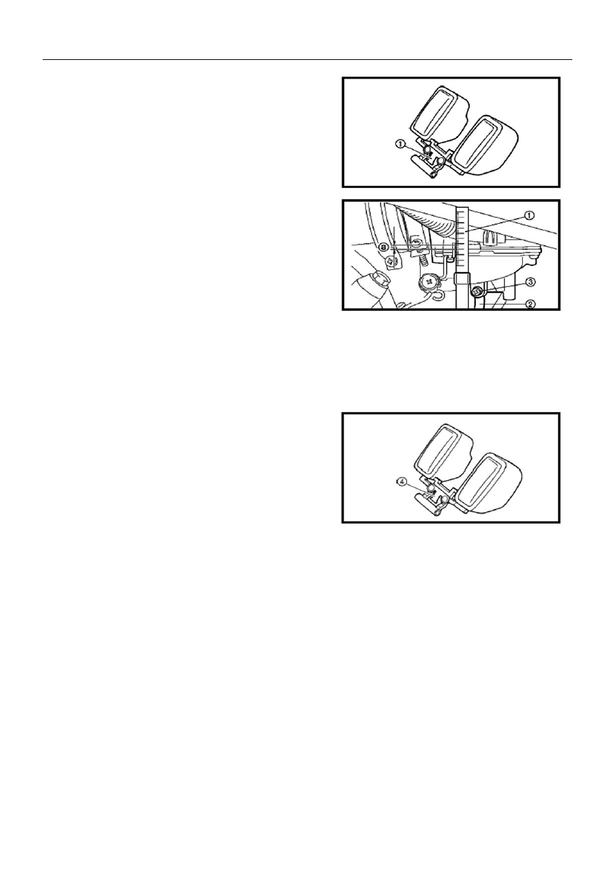
Fuel Level
z
Place carburetor on a level surface. Connect fuel
level gauge
①
with drain pipe
②
;
Tool: Fuel Level Gauge
z
Loosen drain screw
③
z
Keep fuel level gauge vertical next to the float
chamber line and read the fuel level “a”
Fuel Level: 3.5
±
0.5mm
z
If the fuel level is not within the specification, adjust
the fuel level;
z
Remove
carburetor
z
Check valve seat and needle valve
z
If either of valve seat or needle valve is worn,
replace both;
z
If both are fine, adjust float height by bending the
float tang
①
on the float;
z
Install
carburetor
z
Check again the fuel level
Carburetor Assembly
Reverse the disassembly procedure for assembly
16-5