CFMoto ATV CF500-5B, CF500-5C. Service Manual - part 7


  Index      Manuals     CFMoto ATV CF500-5B, CF500-5C. Service Manual


Search            copyright infringement  


Content      ..     5      6      7      8     ..


CFMoto ATV CF500-5B, CF500-5C. Service Manual - part 7


6

-

1

6


Eng

i

n

e


R

e

mo

v

a

l ,   I

n

s

p

ec

ti

on


&

  I

n

s

t

a

l l

a

ti

on


6


6  Engine Removal, Inspection and Installation


!

!

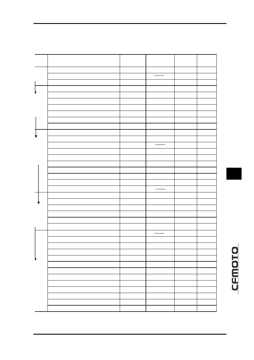
Engine Removal/Installation Orders and the Relative Page Numbers 

tem 

DES 

Disassembly  Inspection / 

Maintenance


Assembly


Remarks 

Water Hose/Pipe


3-2 

2-11 

3-69 


Left Side Cover


3-2 


3-69 


gine 

iphery 


Recoil Starter


3-2 

3-49 

3-68 


Spark Plug


3-2 

2-4 

3-68 


Cylinder Head Cover


3-3 

3-14 

3-66 


Tensioner


3-3 

3-24 

3-67 


Camshaft


3-3 

3-21 

3-65 


Cylinder Head/Tensioner Plate


3-4 

3-15/3-23 

3-64 


Cylinder/Timing Chain Guide


3-4 

3-24/3-23 

3-64 


gine   

nt 

Side   


Piston 

3-5 

3-25 

3-62 


Starting Motor


3-5 

6-3 

3-62 


Oil Filter


3-6 

2-9 

3-62 


Sector Gear


3-6 


3-61 


Water Pump


3-7 

5-7 

3-61 


Sheave Drum


3-7 

3-48 

3-60 


Left Crankcase Cover/ Magneto Stator


3-7 

3-48 

3-60 


Magneto Rotor


3-7 

3-47 

3-60 


Starting Driven Gear


3-8 

3-47 

3-59 


Starting Dual Gear/Idle Gear


3-8 

3-48 

3-59 


ngine 

ft side 


Oil Pump Sprocket and Chain


3-8 


3-59 


CVT Cover 

3-9 

3-51 

3-58 


Drive Belt 

3-9 

3-36 

3-57 


Primary Sheave/Secondary Sheave 

3-9 

3-30 

3-57 


CVT Housing/Clutch Outer Face 

3-10 

3-51 

3-57 


Clutch 

3-10 

3-28 

3-56 


ngine 

ht side 

Timing Chain 

3-10 

3-23 

3-56 


Gear Position Bolt 

3-11 


3-56 


Right Crankcase 

3-11 

3-52 

3-56 


Front Output Shaft Components 

3-11 

3-43 

3-55 


Driven Bevel Gear Components 

3-11 

3-43 

3-55 


Shift Cam 

3-12 

3-40 

3-55 


Guide Bar, Fork 

3-12 

3-39 

3-55 


Drive Bevel Gear Components 

3-12 

3-42 

3-55 


Main Transmission Shaft 

3-12 

3-38 

3-54 


Transmission Counter Shaft 

3-12 

3-38 

3-54 


Balancer Shaft 

3-12 

3-46 

3-54 


Crankshaft 

3-13 

3-27 

3-54 


Oil Pump, Pressure-limiting Valve 

3-13 

3-41 

3-53 


ngine   

enter 

Left Crankcase 


3-52 


es:

 Arrowhead direction is for engine removal orders. Reverse the direction for assembly and 

installation


6

-

2

"

"

Eng

i

n

e


R

e

mo

v

a

l

!

Engine Periphery

Left Side Cover

"

Remove 6 bolts(M6X20) of left side cover

#

$

M6

%

20

&

,

R

e

mo

v

e

  l

e

ft 

s

i

d

e


c

o

v

e

r

#

!

P

r

e

p

a

r

a

ti

on


b

e

f

o

r

e


e

ng

i

n

e

 r

e

mo

v

a

l

"

P

r

e

p

a

r

e


a


p

r

op

e

r   tr

a

y


u

s

e

d

  f

o

r   l

o

a

d


o

f  

c

ompon

e

n

t

s

"

P

r

e

p

a

r

e


n

ece

ss

a

r

y

  r

e

mo

v

a

l  

a

nd


a

ss

e

mb

l

y

  t

oo

l

s

"

D

r

a

i

n


up


e

ng

i

n

e


o

i l

$

3

-

22

&

"

D

r

a

i

n


up


c

oo

l

a

n

t

$

3

-

15

&

"

Remove water hose clamp

'()*

Remove

water hose

+


Water Hose/Pipe

"

Remove screw

,

and water hose

-

Recoil Starter

"

Remove 4 bolts

$

M6

%

12

&

of recoil starter


Remove recoil starter

.


Inspection Plug

"

Remove inspection plug

/

w

it

h


s

c

r

e

wd

ri

v

e

r

!

Engine Front Side


Spark Plug

"

Remove spark plug

0

with special wrench


Tool: Spark Plug Wrench

"

Turn crankshaft, align T.D.C. line A on magneto

rotor with mark B of left crankcase

(

p

i

s

t

on


on


T

.

D

.

C

&

6

-

3

6


Eng

i

n

e


R

e

mo

v

a

l ,   I

n

s

p

ec

ti

on


&

  I

n

s

t

a

l l

a

ti

on


6

"

Remove valve adjusting cover

"

Remove cylinder head cover

"

Remove screw plug

'

, insert a flat screwdriver into

slot of timing chain tensioner adjuster , turn it
clockwise to lock tensioner spring;

"


Remove tensioner fix bolt

"

Remove tensioner and gasket

"

Loosen timing sprocket bolt;


Cylinder Head Cover


Timing Chain Tensioner


Camshaft

"

Remove timing sprocket bolt and lock;

"

Remove12 bolts of cylinder head cover

6

-

4

"

Remove C-ring

'

"

Remove timing sprocket from camshaft, remove

camshaft

"

Remove tensioner plate

"

Remove cylinder head bolt


Cylinder Head

"

Remove cylinder head bolts diagonally;

"

Remove cylinder head

"

Remove dowel pin and cylinder head gasket


Cylinder

"

Remove timing chain guide

'

No

t

e

:  

T

ake


ca

r

e


no

t   t

o


d

r

op


dow

e

l

p

i

n

  i

n

t

o


c

r

a

n

kca

s

e

Note: Take care not to drop spacer, bolt, bolt lock
and C-ring into crankcase.

6

-

5

6


Eng

i

n

e


R

e

mo

v

a

l ,   I

n

s

p

ec

ti

on


&

  I

n

s

t

a

l l

a

ti

on


6

"

Remove cylinder bolt

"

Remove cylinder

"

Remove dowel pin and cylinder gasket

"

Remove piston pin circlip

'

with long nosed pli-

ers


Piston

Note

#

#

Put a clean rag under piston so as not to

drop piston pin circlip into crankcase

N o t e

#

#

"

When installing piston, make sure its

identification conforms to that of cylinder

"

When removing piston pin, clean off burrs of

piston pin hole and groove. If it is difficult to
remove the piston, DO NOT hammer, use a
special remover

,

"

Remove piston pin

)

and piston

+

!

!

Engine Left Side


Starting Motor

"

Remove 2 bolts of starting motor

"

Remove starting motor


Tool: Piston Pin Remover

Note

#

#

When performing above removal process,

be sure to hook up timing chain to
prevent it from falling into crankcase

Note

#

#

Take care not to drop dowel pin into

crankcase

6

-

6


Oil Filter

"

R

emove oil filter with special tools


Tool: Oil filter Remover

"

Remove bolt 1 of gearshift rocker arm


Sector Gear

"

Remove gasket 2 and gearshift rocker arm 3

"

Remove bolt of sector gear housin cover

"

Remove wire clip and sector gear housing cover

"

Remove dowel pin and gasket

"

Remove drive sector gear 4

"

Remove bolt 5 of driven sector gear

"

Remove washer 6 and driven sector 7

6

-

7

6


Eng

i

n

e


R

e

mo

v

a

l ,   I

n

s

p

ec

ti

on


&

  I

n

s

t

a

l l

a

ti

on


6

"

Screw out bolt of water pump

"

Remove water pump


Water Pump

Sheave Drum

"

Remove the sheave drum by using a suitable bar;

"

Remove washer and sheave drum


Left Crankcase Cover

"

Remove bolts;

"

Remove left crankcase cover

"

Remove dowel pin and gasket


Magneto Rotor

"

Install attachment 1 to crankshaft end

"


Install special tool to rotor thread;


Remove rotor and woodruff key


Tool: Rotor Remover

6

-

8

"

Remove driven gear 1 and needle bearing

Starting Motor Gear

"

Remove idle gear and shaft 4

"

Remove dual gear and shaft 3


Oil Pump Sprocket and Chain

"

Remove spacer 2

"

Remove drive sprocket nut 5

"

Remove C-ring 6

"

Remove oil pump drive and driven sprockets and

chain

6

-

9

6


Eng

i

n

e


R

e

mo

v

a

l ,   I

n

s

p

ec

ti

on


&

  I

n

s

t

a

l l

a

ti

on


6

!

Engine Right Side


CVT Cover

"

Remove bolt of CVT cover

"

Remove CVT cover

"

Remove gasket and dowel pin


CVT(Continuously Variable Transmission)

"

Remove primary sheave nut with special tool

"

Remove primary sliding sheave

"

Remove secondary sheave nut with special tools

"

Remove secondary sheave


Tool: Sheave Holder

"

Remove drive belt

"

Remove primary fixed sheave

'

"

Remove bolt for air guide plate,Remove air guide

plate

6

-

10


CVT Case

"

Remove bolt 1 of CVT case

"

Remove outer clutch face and CVT case


Clutch

"

Remove clutch shoe fixing nut with special tool

"

Remove dowel pin, front and rear gasket

"

Remove clutch shoe


Note

#

#

The clutch shoe nut has left-hand threads


Timing Chain

"

Remove timing chain

"

Remove nut 2 of CVT case

6

-

11

6


Eng

i

n

e


R

e

mo

v

a

l ,   I

n

s

p

ec

ti

on


&

  I

n

s

t

a

l l

a

ti

on


6

"

Remove left crankcase bolts

"

Remove right crankcase bolts

"

Separate right crankcase with special tool

"

The Crankcase separator plate

should be parallel with the end face
of crankcase

"

Crankshaft should remain in the left

crankcase half.


Tool: Crankcase separator


Driven Bevel Gear, Front Output Shaft

"

Remove bevel gear cover bolt

"

Remove driven bevel gear

+

"

Remove front output shaft nut

,

!

Engine Center

Gear position bolt

"

Remove gear position bolt

'

"

Remove spring and steel ball

Caution

Right Crankcase

6

-

12

"

Remove left crankcase from driven bevel gear

Shift Cam, Fork/Shaft


Drive Bevel Gear

"

Remove Shift Cam

-(

Fork /Shaft

#1


Balancer Shaft

"

Remove balancer shaft

1

Drive Shaft, Drive Shaft

"

Remove Oil  seal

'(

Bearing  limit  nut 

)

$

l

e

f t   r

o

l l

&

"

Remove Front Output Shaft

,

"

Remove drive shaft

.

and driven shaft

/

6

-

13

6


Eng

i

n

e


R

e

mo

v

a

l ,   I

n

s

p

ec

ti

on


&

  I

n

s

t

a

l l

a

ti

on


6

"

Remove oil bump and relief valve

1

Oil bump, Relief Valve

"

Separate crankshaft from left crankcase with spe-

cial tool

Crankshaft


Tool: Crankshaft Separator

6

-

14

$

$

Engine Components Inspection


Cylinder Head Cover


!

!

Disassembly

Caution

#

#

Each removed part should be identi-

fied to its location, and the pars should be laid out
in groups designated as 

¡°

Exhaust

¡±

¡°

Intake

¡±

, so

that each will be restored to the original location
during assembly.

"

Remove rocker arm shaft bolts


A

"

Remove rocker arm shaft by using M6 bolts 

B


Cylinder Head Cover Distortion


Clean off sealant from the fitting surface of cylin-

der head cover, place cylinder head cover on a sur-
face plate and measure distortion with a thickness
gauge.


Cylinder head Cover Distortion


Limit: 0.05mm


Tool: Thickness Gauge


Distortion out of range: 

--

Replace


Rocker Arm Shaft


"

Measure out diameter of rocker arm shaft with a

micrometer.

Rocker Arm Shaft O.D.: (IN, EX)
Limit: 11.973~11.984mm
Tool: Micrometer (0~25mm)

Note

#

#

Cylinder head cover and cylinder head

should be replaced together.

6

-

15

6


Eng

i

n

e


R

e

mo

v

a

l ,   I

n

s

p

ec

ti

on


&

  I

n

s

t

a

l l

a

ti

on


6


Rocker Arm


"

When checking the rocker arm, check the inner

diameter of the valve rocker arm and wear of the
camshaft contact surface.


"

Rocker Arm I.D. : 

.000~12.018mm


Tool: Dial Calipers


!

!

Assembly


Cylinder Had


Note

#

#

Intake rocker arm shaft A has oil holes.

"

Apply engine oil to rocker arms and shafts;

"

Install rocker arms and tighten rocker arm shaft to

the specified torque:


Rocker Arm Shaft Bolt: 28N.m


!

!

Disassembly

"

Remove intake pipe

"

Remove water temperature sensor

'

and

thermostat cover

)

6

-

16

"

Remove thermostat

"

Compress the valve spring and remove valve cotter

with tweezers.

"

Remove valve spring upper seat and valve spring


Tools: Valve Spring Compressor


Tweezers

"

Remove valve from the other side.

"

Remove valve stem seal ring and valve lower seat.


Content      ..     5      6      7      8     ..