CFMoto motorcycle CF650NK. Service Manual - part 24


  Index      Manuals     CFMoto motorcycle CF650NK. Service Manual


Search            copyright infringement  


Content      ..     22      23      24      25     ..


CFMoto motorcycle CF650NK. Service Manual - part 24


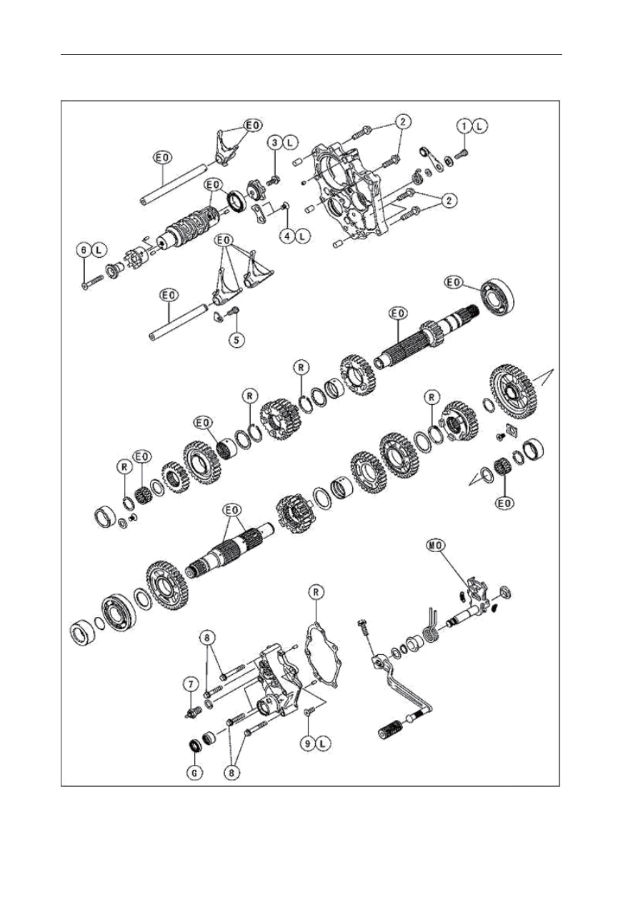
9-4 CRANKSHAFT/TRANSMISSION

Exploded View

-------------------------------------------------------------------------------------------------------------------------------------------------------------

CRANKSHAFT/TRANSMISSION 9-5

Exploded View

No.

Fastener

Torque

Remarks

N·m

kgf·m

ft·lb

1

Gear Positioning Lever Bolt

12

1.2

106in·lb

L

2

Transmission Case Bolts

20

2.0

15

3

Shift Drum Cam Bolt

12

1.2

106in·lb

L

4

Shift Drum Bearing Holder Screw

 5

0.50

43in·lb

L

5

Shift Rod Plate Bolt

10

1.0

87in·lb

6

Neutral Switch Holder Screw

 5

0.50

43in·lb

L

7

Neutral Switch

15

1.5

11

8

Shift Shaft Cover Bolts

12

1.0

87in·lb

9

Shift Shaft Cover Screw

 5

0.50

43in·lb

L

EO:  Apply engine oil. 

G:   Apply grease.

L:   Apply a non-permanent locking agent. 

MO:  Apply molybdenum disul

fi

 de oil solution.


(mixture of the engine oil and molybdenum disul

fi

 de grease in a weight ratio 10 : 1) 

R:   Replacement Parts

-------------------------------------------------------------------------------------------------------------------------------------------------------------

9-6 CRANKSHAFT/TRANSMISSION

Item

Standard

Service Limit

Crankshaft, Connecting Rods

Connecting Rod Bend

         0.04/100mm

0.2/100mm

Connecting Rod Twist

         0.08/100mm

0.2/100mm

Connecting Rod Big End Side Clearance

0.15 ~ 0.30mm

0.55mm

Connecting Rod Big End Bearing Insert/
Crankpin Clearance

0.02 ~ 0.04mm

0.08mm

Crankpin Diameter:

37.984 ~ 38.00mm

37.97mm

     Marking:

2

 37.984 ~ 37.992mm

– – –

1

 37.993 ~ 38.000mm

– – –

 Connecting Rod Big End Inside Diameter:

 41.000 ~ 41.016mm

– – –

     Marking:

1

 41.000 ~ 41.008mm

– – –

2

 41.009 ~ 41.016mm

– – –

 Connecting Rod Big End Bearing Insert Thickness:

 Marking:

  Black

1.485 ~ 1.490mm

– – –

  Blue

1.490 ~ 1.495mm

– – –

  Green

1.495 ~ 1.500mm

– – –

 Connecting Rod Big End Bearing Insert Selection:

Con-rod Big End Bore 

Diameter Marking

Crankpin Diameter Marking

          Bearing Insert

1

1

    Black

1

2

Blue

2

1

2

2

     Green

Specifi catons

-------------------------------------------------------------------------------------------------------------------------------------------------------------

CRANKSHAFT/TRANSMISSION 9-7

Item

Standard

Service Limit

Crankshaft/Upper Crankcase Clearance

0.05 ~ 0.25mm

0.40mm

Crankshaft Runout

0.02mm

0.05mm

 Crankshaft Main Bearing Insert/Journal Clearance

0.02 ~ 0.04mm

0.07mm

 Crankshaft Main Journal Diameter:

37.984 ~ 38.00mm

37.96mm

 Marking:

2

37.984 ~ 37.992mm

– – –

1

37.993 ~ 38.000mm

– – –

 Crankcase Main Bearing Inside Diameter:

41.000 ~ 41.016mm

– – –

 Marking:

Blue

41.000 ~ 41.008mm

– – –

None

 41.009 ~ 41.016mm

– – –

 Crankshaft Main Bearing Insert Thickness:

 Marking:

Brown

1.496 ~ 1.500mm

– – –

Black

1.500 ~ 1.504mm

– – –

Blue

1.504 ~ 1.508mm

– – –

Crankshaft Main Bearing Insert Selection:

Crankcase Main 

Bearing Bore Diameter 

Marking

Crankshaft Main Journal Diameter Marking

         Bearin 

Insert

Blue

1

Brown

Blue

2

Black

None

1

None

2

 Blue

 Balancer Shaft Bearing Insert/Journal Clearance

0.02 ~ 0.04mm

0.07mm

 Balancer Shaft Journal Diameter:

27.987 ~ 28.00mm

27.96mm

 Marking:

1

27.987 ~ 27.993mm

–––

2

27.993 ~ 28.000mm

–––

Specifi cations

-------------------------------------------------------------------------------------------------------------------------------------------------------------

9-8 CRANKSHAFT/TRANSMISSION

 Crankcase Bearing Bore Diameter:

31.000 ~ 31.016mm

–––

 Marking:

Blue

31.000 ~ 31.008mm

–––

None

31.009 ~ 31.016mm

–––

 Balancer Shaft Bearing Insert Thickness:

 Marking:

Brown

1.490 ~ 1.494mm

–––

Black

1.494 ~ 1.498mm

–––

Blue

1.498 ~ 1.502mm

–––

 Balancer Shaft Bearing Insert Selection
 Crankcase Bearing Bore      

Diameter Marking

Balancer Shaft Journal 

Diameter Marking

Bearing Insert

Blue

2

Brown

Blue

1

Black

None

2

None

1

Blue

 Transmission

 Shift Fork Ear Thickness

5.9 ~ 6.0mm

5.8mm

 Gear Groove Width

6.05 ~ 6.15mm

6.25mm

 Shift Fork Guide Pin Diameter

6.90 ~ 7.0mm

6.8mm

 Shift Drum Groove Width

7.1 ~ 7.15mm

7.3mm

Specifi cations

-------------------------------------------------------------------------------------------------------------------------------------------------------------

CRANKSHAFT/TRANSMISSION 9-9

Special Tools

Outside Circlip Pliers                                                     Silicone Sealant

Bearing Driver Set

-------------------------------------------------------------------------------------------------------------------------------------------------------------

9-10 CRANKSHAFT/TRANSMISSION

Crankcase Splitting

Crankcase Splitting

 Remove:

   Engine (see Engine Removal in the Engine  
   Removal/Installation chapter)
   Cylinder (see Cylinder Removal in the Engine 
   Top End chapter)
   Pistons (see Piston Removal in the Engine Top 
   End chapter)
   Stater Motor (see Starter Motor Removal in the 
   Electrical System chapter)
   Clutch (see Clutch Removal in the Clutch 
   chapter) 
   Transmission Assy (see Transmission Assy 
   Removal) 
   Alternator Rotor (see Alternator Rotor Re
   moval in the Electrical System chapter)

 Remove the upper crankcase bolts [A] and the 

   washers.

 Remove the oil pan, relief valve, oil screen and

   oil pipes (see Oil Pan Removal in the Engine 
   Lubrication System chapter).

 Remove the lower crankcase bolts.

 Firstly loosen the M7 bolts, secondly the M8 bolts 

   and lastly the M9 bolts.
   M7 Bolts [A] 
   M8 Bolts [B]
   M9 Bolts [C] and Washers

-------------------------------------------------------------------------------------------------------------------------------------------------------------

CRANKSHAFT/TRANSMISSION 9-11

Crankcase Splitting

 Tap lightly around the crankcase mating surface 

   with a plastic mallet, and split the crankcase. 
    Take care not to damage the crankcase.

    If the oil pipe is to be removed, follow the next 
    procedure.

  Unscrew the bolts [A] and remove the oil pipe [B].

 Prepare a 5 mm rod [A], and insert it to the hole 

   of the upper crankcase half.

 Remove the oil pipe [B], tapping [C] the rod as 

   shown.

   If the breather plate [A] is to be removed, follow 
   the next procedure.

 Remove the oil pipe (see above).

 Cut the gasket around the plate [B].

 Remove:

       Breather Plate Bolts [C]
       Breather Plate with Pipe

-------------------------------------------------------------------------------------------------------------------------------------------------------------

9-12 CRANKSHAFT/TRANSMISSION

Crankcase Splitting

Crankcase Assembly

CAUTION

The upper and lower crankcase halves are ma- 
chined at the factory in the assembled state, 
so the crankcase halves must be replaced as 
a set.

 With a high-flash point solvent, clean off the 

   mating surfaces of the crankcases halves and 
    wipe dry.

 Using compressed air, blow out the oil passages 

   in the crankcase halves.

 If the oil plate [A] on the upper crankcase half 

   was removed, install it as shown.

 Apply a non-permanent locking agent to the oil 

   plate bolts and torque them.


  Torque - Oil Plate Bolts [B]: 10 N·m (1.0 N·m, 

   87 in·lb)

 Press and insert [A] the new needle bearing [B] 

   for the shift drum until it is bottomed.


Special Tool -  Bearing Driver Set

 Press and insert [C] the new needle bearing [D] 

   for the shift shaft so that the bearing surface is 
   

fl

 ush with the end of the hole.


 Special Tool -  Bearing Driver Set

  Lower Crankcase Half [E]

 Apply silicone sealant to the breather plate 

   mating surface [A] 1 mm (0.04 in.)  or more thick, 
   and then install the breather plate.
 

NOTE


Make the application 

fi

 nish within 7 minutes when 

   the liquid gasket to the mating surface of the 
   breather plate is applied.

-------------------------------------------------------------------------------------------------------------------------------------------------------------

CRANKSHAFT/TRANSMISSION 9-13

Crankcase Splitting

 Moreover 

fi

 t the plate and tighten the bolts just 

   after application of the liquid gasket. 

 Apply a non-permanent locking agent to the  

   threads and tighten the bolts [A].

   Torque - Breather Plate Bolts: 10 N·m (1.0 kgf·
    m, 87 in·lb)

 Install the breather pipe [A].

 Align the white mark [B] on the pipe with the 

   white mark [C] on the breather 

fi

 ttling.

 Install the clamp [D] so that the pinch portions [E] 

   face the white marks.

 Install the oil pipe [A] so that its flange [B] 

  touches to the surface [C] of the upper 
    crankcase half.

 Apply grease to the O-ring [D] on the oil pipe.

-------------------------------------------------------------------------------------------------------------------------------------------------------------

9-14 CRANKSHAFT/TRANSMISSION

Crankcase Splitting

 Install the crankshaft assembly and the balancer 

   shaft assembly on the upper crankcase half.

 Align [A] the timing mark on the balancer gear [B] 

   with the timing mark on the balancer drive gear [C] 
   of the crankshaft.

 Be sure to hang the camshaft chain [A] on the 

   crankshaft.

 Be sure that the dowel pins [A] are in position.

 Set the bearing groove [A] on the positioning ring 

   [B] as shown.

-------------------------------------------------------------------------------------------------------------------------------------------------------------

CRANKSHAFT/TRANSMISSION 9-15

Crankcase Splitting


Apply liquid gasket [A] to the mating surface of 

   the lower crankcase half.

NOTE


Apply the sealant evenly on the mating surfcae.

CAUTION

D o   n o t   a p p l y   l i q u i d   g a s k e t   a r o u n d   t h e 
crankshaft main bearing inserts, and oil 
passage holes.

 Do not apply liquid gasket to the oil passage [B].

-------------------------------------------------------------------------------------------------------------------------------------------------------------

9-16 CRANKSHAFT/TRANSMISSION

Crankcase Splitting

 Fit the lower crankcase half to the upper 

    crankcase half.

 Insert [A] the breather pipe [B] on the upper 

   crankcase half  through the hole [C] on the lower 
   crankcase half.

NOTE


Make the application finish within 20 minutes 

  when the liquid gasket to the mating surface of 
   the lower crankcase half is applied.


Moreover 

fi

 t the case and tighten the case bolts  

   just after 

fi

 nishing the application of the liquid 

   gasket.

 The M9 bolts [1 ~ 6] (see the next 

fi

 gure)  have 

   copper plated washers. Replace them with new 
    ones.

 Apply molybdenum disulfide oil solution to both 

   sides [A] of the M9 bolts washers and the threads 
   [B] of the M9 bolts.

 Apply molybdenum disul

fi

 de oil solution to 

fl

 ange 

  [A] and the threads [B] of the M8 bolts which is 
  tightening order is [7~10] only (see the next 
   

fi

 gure).


-------------------------------------------------------------------------------------------------------------------------------------------------------------

CRANKSHAFT/TRANSMISSION 9-17

Crankase Splitting

 Tighten the lower crankcase bolts using the 

    followwing steps.

 Tighten the M9 bolts [1, 2] L= 113 mm (4.45 in.) 

   with washers.
   Torque - Crankcase Bolts (M9): 44 N·m (4.5 
    kgf·m, 32 ft·lb)

 Tighten the M9 bolts [3, 4] L= 83 mm (3.27 in.) 

    with washers.
   Torque - Crankcase Bolts (M9): 44 N·m (4.5 
    kgf·m, 32 ft·lb)

 Tighten the M9 bolts [5, 6] L= 113 mm (4.45 in.)  

   with washers.
   Torque - Crankcase Bolts (M9): 44 N·m (4.5 kgf·
  m, 32 ft·lb)

 Tighten the M8 bolts [7~10].

   Torque - Crankcase Bolts (M8): 35 N·m (3.6 
   kgf·m, 26 ft·lb)

 Tighten the M8 bolts [A] (Do not apply 

molybdenum 
   oil solution).
   Torque - Crankcase  Bolts  (M8):   27.5  N·m  (2.
   8  kgf·m,  20 ft·lb)

 Tighten the M7 bolts [B].

   Torque - Crankcase  Bolts  (M6):   20 N·m  (2.
   0  kgf·m,  15 ft·lb)

 Tighten the upper crankcase bolts [A].

 The upper crankcase bolts have copper plated 

   washers. Replace them with new ones.
   Torque - Upper Crankcase  Bolts [A]: 27.5 N·m 
   (2.8 kgf·m,

 After tightening all crankcase bolts, check the fol-

   lowing items.

 Crankshaft and balancer shafts turn freely.

-------------------------------------------------------------------------------------------------------------------------------------------------------------

9-18 CRANKSHAFT/TRANSMISSION

Crankshaft and Connecting Rods

Crankshaft Removal

 Split the crankcase (see Crankcase Splitting).

 Remove the crankshaft [A].

Crankshaft Installation

CAUTION

 If  the  crankshaft,  bearing inserts,  or  
crankcase halves are replaced with new ones, 
select the bearing inserts and check clearance 
with a plastigage (press gauge) before 
assembling engine to be sure the correct 
bearing inserts are installed.

 Apply molybdenum disul

fi

 de oil solution to the 

  crankshaft main bearing inserts.

 Align [A] the timing mark on the balancer gear 

  [B] with the timing mark on the balancer drive 
  gear [C] of the crankshaft.

 Install the crankshaft with the camshaft chain 

   [A] hanging on it.

-------------------------------------------------------------------------------------------------------------------------------------------------------------

CRANKSHAFT/TRANSMISSION 9-19

Crankshaft and Connecting Rods

Connecting Rod Removal

 Split the crankcase (see Crankcase Splitting).

 Remove the connecting rod nuts [A].

 Remove the connecting rod.

 Remove the connecting rod bolts.

CAUTION

To prevent damage to the crankpin surfaces, 
do not allow the connecting rod bolts to bump 
against the crankpins.

Connecting Rod Installation

CAUTION

To minimize vibration, the connecting rods 
should have the same weight mark. Always 
use new connecting rod bolts and nuts.

Match Mark [A] 
Connecting Rod [B]
Diameter Mark  [C] 
Weight Mark [D]
Connecting Rod Big End Cap [E]

CAUTION

If the connecting rods, big end bearing 
inserts, or crankshaft are replaced with new 
ones, select the bearing insert and check 
clearance with a plastigage (press gauge) 
before assembling engine to be sure the 
correct bearing inserts are installed.

-------------------------------------------------------------------------------------------------------------------------------------------------------------


Content      ..     22      23      24      25     ..