Hyundai Excavator R210LC-7. Service and repair manual - page 21


  Index      Manuals     Hyundai Excavator R210LC-7. Service and repair manual


Search            copyright infringement  


Content      ..     19      20      21      22     ..


Hyundai Excavator R210LC-7. Service and repair manual - page 21


6 - 30

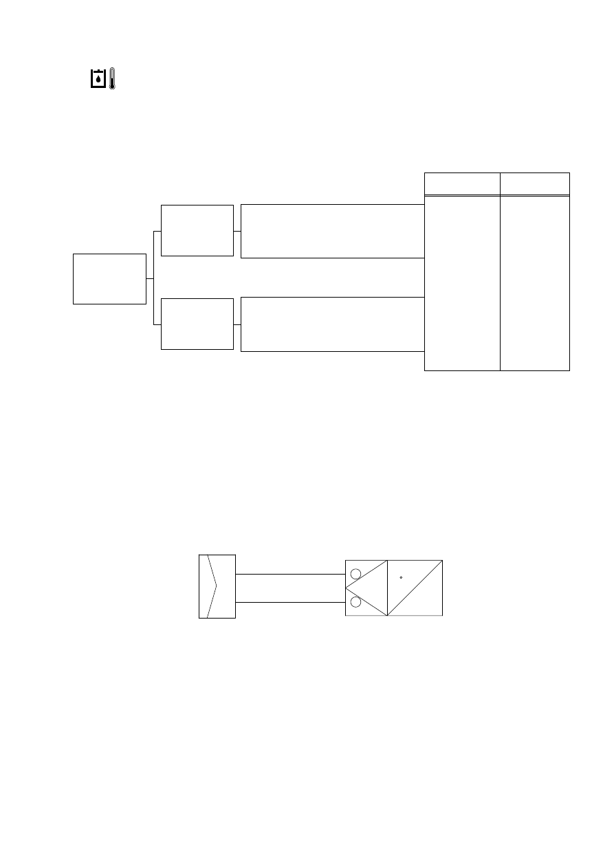
7.                 WHEN HYDRAULIC OIL TEMPERATURE WARNING LAMP LIGHTS UP

(Engine is started)

Before disconnecting the connector, always turn the starting switch OFF.
Before carrying out below procedure, check all the related connectors are properly inserted.
After checking, insert the disconnected connectors again immediately unless otherwise specified.

Cause

Remedy

High temperature

Defective torque
sensor

Short circuit

Defective controller

Check hydraulic
oil temperature
(100 C

2 C )  ,

Replace
Replace

Check and repair

Replace

HYDRAULIC OIL 
TEMPERATURE SENDER

CD-1

C

2

1

CN-51

34

CONTROLLER

31

Starting switch : ON
Engine : Start

Does display go
off when
disconnect CD-1?

Resistance
between CN-51
(31,34) is 0~1 ? 

Starting switch : OFF
Disconnect CN-51

Resistance
between CD-1
(1,2) is in range
of 130~150 ?

Starting switch : ON
Disconnect CD-1

YES

YES

YES

NO

NO

NO

29076ES04

6 - 31

8.                WHEN COOLANT LEVEL WARNING LAMP LIGHTS UP

(Engine is started)

Before disconnecting the connector, always turn the starting switch OFF.
Before carrying out below procedure, check all the related connectors are properly inserted.
After checking, insert the disconnected connectors again immediately unless otherwise specified.

Cause

Remedy

Insufficient coolant
or Defective switch

Short circuit

Defective controller

Refill coolant or
replace switch

Check and repair

Replace

CN-50

18

CD-16

1

2

COOLANT LEVEL SENSOR

CONTROLLER

YES

Starting switch : ON
Engine : Start

Does display go
off when
disconnect CD-
16?

Check resistance
between CN-51
(15) and chassis

Starting switch : OFF
Disconnect CN-51

YES

NO

MAX 1

MIN 1M

Check resistance

YES

NO

NO

15

51

25036EL08

6 - 32

9.  WHEN COOLANT TEMPERATURE GAUGE DOES NOT OPERATE

Before disconnecting the connector, always turn the starting switch OFF.
Before carrying out below procedure, check all the related connectors are properly inserted.
After checking, insert the disconnected connectors again immediately unless otherwise specified.

Cause

Remedy

Disconnection in
wiring harness or
poor contact
between 
CN-51-CD-8

Defective controller

Defective temp
sensor

Defective cluster

Repair or replace
(After clean)

Replace

Replace

Replace

YES

YES

YES

NO

NO

NO

Temperature

White range

(~29 C)

Green range

(30~105 C)

Red range

(105 C ~)

Check Table

Item

Unit Resistance( )

Tolerance(%)

1646~

20 

1645~158

20 

~139

20

Starting switch : ON

Does the gauge
light up and
down at lamp
check?

Is resistance
between CN-51
(31) and (33)
over 2k ?

Starting switch : OFF
Disconnect CN-50

See Table

Check resistance
between CN-3(2)
,(5) and (7),(6)

Green range Red range

White range

21076ES53

6 - 33

10.  WHEN FUEL GAUGE DOES NOT OPERATE

(Check warning lamp ON/OFF)

Before disconnecting the connector, always turn the starting switch OFF.
Before carrying out below procedure, check all the related connectors are properly inserted.
After checking, insert the disconnected connectors again immediately unless otherwise specified.

FUEL SENDER

CD-2

24

CN-51

31

2

1

CONTROLLER

Level

White range

Green range

Red range

Check Table

Item

Unit Resistance( )

Tolerance(%)

700~601

5

600~101

5

~100

5

Cause

Remedy

Disconnection in
wiring harness

Defective controller

Defective fuel
sensor

Defective cluster

Check and repair

Replace

Replace

Replace

YES

YES

Starting switch : ON

Does the gauge
light up and
down at lamp
check?

Is resistance
between CN-51
(24) and (31)
over 1k ?

Starting switch : OFF
Disconnect CN-51

Disconnect CD-2
See Table

Check resistance
between CD-2(1)
and (2)

YES

NO

NO

NO

Green range Red range

White range

29076ES06

6 - 34

11.  WHEN SAFETY SOLENOID DOES NOT OPERATE

Before disconnecting the connector, always turn the starting switch OFF.
Before carrying out below procedure, check all the related connectors are properly inserted and

short of fuse No.24.

After checking, insert the disconnected connectors again immediately unless otherwise specified.

Cause

Remedy

Hydraulic
malfunction

Defective solenoid

Disconnect in
wiring harness or
poor contact
between 
CN-4(8)-CS-4(C)

Disconnect in
wiring harness or
poor contact
between 
CN-4(8)-CN-68(1)

Disconnection in
fuse

Defective switch
(CS-20)

Defective switch
(CS-4)

Check hydraulic
system

Replace

Repair or replace
(After clean)

Repair or replace
(After clean)

Replace

Repair or replace

Repair or replace

Check voltage
between CN-68
(1) - CN-68(2) 

YES

YES

YES

YES

NO

NO

NO

NO

NO

Safety lever : OFF
Starting switch : ON
Voltage : 20~30V

NO

Check operation
of solenoid

Safety lever : ON-OFF

Starting switch : ON
Voltage : 20~30V
Disconnect CN-4

Starting switch : ON
Voltage : 20~30V
Disconnect CN-4

Starting switch : ON
Voltage : 20~30V

Starting switch : ON
Voltage : 20~30V
Safety state

Check voltage
between CN-68
(2) with chassis

Check voltage
between CS-4
(C) and chassis

Check voltage
between CS-20
and chassis

Check voltage
between CN-4(8)
and chassis

YES

YES

21076ES54

6 - 35

12.  WHEN TRAVEL SPEED 1, 2 DOES NOT OPERATE

Before disconnecting the connector, always turn the starting switch OFF.
Before carrying out below procedure, check all the related connectors are properly inserted and

short of fuse No.22 .

After checking, insert the disconnected connectors again immediately unless otherwise specified.

TRAVEL SOLENOID

CN-70

1

2

FUSE

NO.22

13

CN-50

CONTROLLER

YES

NO

Check if travel
speed lamps(        ,

) change when

pressing the travel
speed switch on
the cluster

Check controller

Cause

Remedy

Defective hydraulic
system

Defective controller

Defective solenoid

Defective cluster

Defective controller

Check hydraulic
system

Replace

Replace

Replace

Replace

Check operation
of solenoid

Check resistance
between CN-70
(1) and (2)

Starting switch : ON

Starting switch : ON
Volage : 20~30V
Disconnect CN-50

Starting switch : ON

: OFF
: ON

Starting switch : OFF
SPEC : 15~25
Disconnect CN-70

Starting switch : ON

Check voltage
between CN-50
(13) and chassis

YES

R

Y

G

YES

YES

YES

NO

NO

NO

21076ES04

13. WHEN ENGINE DOES NOT START

Check supply of the power at engine stop solenoid while starting switch is ON.
Before disconnecting the connector, always turn the starting switch OFF.
Before carrying out below procedure, check all the related connectors are properly inserted.
After checking, insert the disconnected connectors again immediately unless otherwise specified.

6 - 37

14. WHEN STARTING SWITCH “ON” ELECTRIC PART DOES NOT OPERATE

Before disconnecting the connector, always turn the starting switch OFF.
Before carrying out below procedure, check all the related connectors are properly inserted and

master switch ON

After checking, insert the disconnected connectors again immediately unless otherwise specified.

15. WHEN STARTING SWITCH IS TURNED ON, WIPER MOTOR DOES NOT OPERATE

Before disconnecting the connector, always turn the starting switch OFF.
Before carrying out below procedure, check all the related connectors are properly inserted and the fuse

No.4,11 and 13 is not blown out.

After checking, insert the disconnected connectors again immediately unless otherwise specified.

6 - 39

16. WHEN STARTING SWITCH IS TURNED ON, HEAD LAMP DOES NOT LIGHTS UP

Before disconnecting the connector, always turn the starting switch OFF.
Before carrying out below procedure, check all the related connectors are properly inserted and

short of fuse No.14.

After checking, insert the disconnected connectors again immediately unless otherwise specified.

29076ES12

6 - 40

17. WHEN STARTING SWITCH IS TURNED ON, WORK LAMP DOES NOT LIGHTS UP

Before disconnecting the connector, always turn the starting switch OFF.
Before carrying out below procedure, check all the related connectors are properly inserted and

short of fuse No.15.

After checking, insert the disconnected connectors again immediately unless otherwise specified.

29076ES13

GROUP  4  MECHATRONICS SYSTEM(up to #1000)

1. ALL ACTUATORS SPEED ARE SLOW(up to #0179)

6 - 41-1

Wiring diagram

1-1.  ALL ACTUATORS SPEED ARE SLOW(from #0180 to #1000)

Boom, Arm, Bucket, Swing and travel speed are slow, but engine speed is good.
Spec : H-mode

2250

50rpm

S-mode

2150 

50rpm

Before carrying out below procedure, check all the related connectors are properly inserted.

INSPECTION PROCEDURE

1)

SPEC : 200~550mA
See TEST 3

SPEC : 5~20kgf/cm

2

See TEST 4

SPEC : 17.5 1 (20 C)
See TEST 2

Check if 

Er : 03

on the cluster

Check electric 
current at EPPR
valve

Check resistance 
at EPPR valve

Check pressure 
at EPPR valve

YES

YES

YES

YES

NO

NO

NO

NO

Cause

Remedy

Defective
hydraulic system

Defective
EPPR valve

Defective CPU
controller

Short circuit or
poor connection
between CN-50 -
CN-75

Defective EPPR
valve

Replace

Replace

Check and repair
wire harness or
between CN-50-
CN-75

Replace

21076MS51

6 - 42

TEST PROCEDURE

Test 1 :

Check resistance at connector
CN-50(8)-(36).

Starting key OFF.
Disconnect connector CN-50.
Check resistance between pin and at
connector CN-50(8)-(36).

CPU

CONTROLLER

CN-50

Y R G

CN-51

Multimeter

CN-50

1

12

8

25

36

13

24

CN-75

Multimeter

CN-75

Multimeter

EPPR VALVE

(1)

2)

Test 2 :

Check resistance at connector
CN-75.

Starting key OFF.
Disconnect connector CN-75 from EPPR
valve at main hydraulic pump.
Check resistance between 2 lines as
figure.

(2)

Test 3 : 

Check electric current at EPPR valve.

Install multimeter as figure.
Start engine.
Set the accel dial at "10"(MAX)
Set S-mode and cancel auto decel mode.
If tachometer show approx 2150 50rpm,
check electric current.

(3)

SPEC : 17.5 1 (20 C )

SPEC : 17.5 1 (20 C)

SPEC : 200~550mA (S mode)

29076MS02

(210-7)  6-38(2)

(210-7)  6-38(3)

6 - 43

CN-75

Supply line, pilot press

Pressure adjusting
screw locknut

SPEC : 5~20kgf/cm

2

(70~280psi)

Test 4 : 

Check pressure at EPPR valve.

Remove plug and connect pressure
gauge as figure.

Gauge capacity : 0 to 40~50kgf/cm

2

(0 to 570~710psi)

Start engine.
Set the accel dial at "10"(Max)
Set S-mode and cancel auto decel mode.
If tachometer show approx 2150 50rpm,
check pressure.
If pressure is not correct, adjust it.
After adjust, test the machine.

(2)

(210-7)  6-39(1)

2.  ENGINE SPEED IS SLOW AT ALL MODE

Before carrying out below procedure, check all the related connectors are properly inserted.

INSPECTION PROCEDURE

1)


Content      ..     19      20      21      22     ..