Hyundai Excavator R450LC-7. Service and repair manual - page 15
4-39
No. of
pin
Receptacle connector(Female)
Plug connector(Male)
12
1
7
6
12
174045-2
AMP 040 MULTILOCK CONNECTOR
8)
No. of
pin
Receptacle connector(Female)
Plug connector(Male)
14
1
7
6
14
173852
AMP 070 MULTILOCK CONNECTOR
9)
No. of
pin
Receptacle connector(Female)
Plug connector(Male)
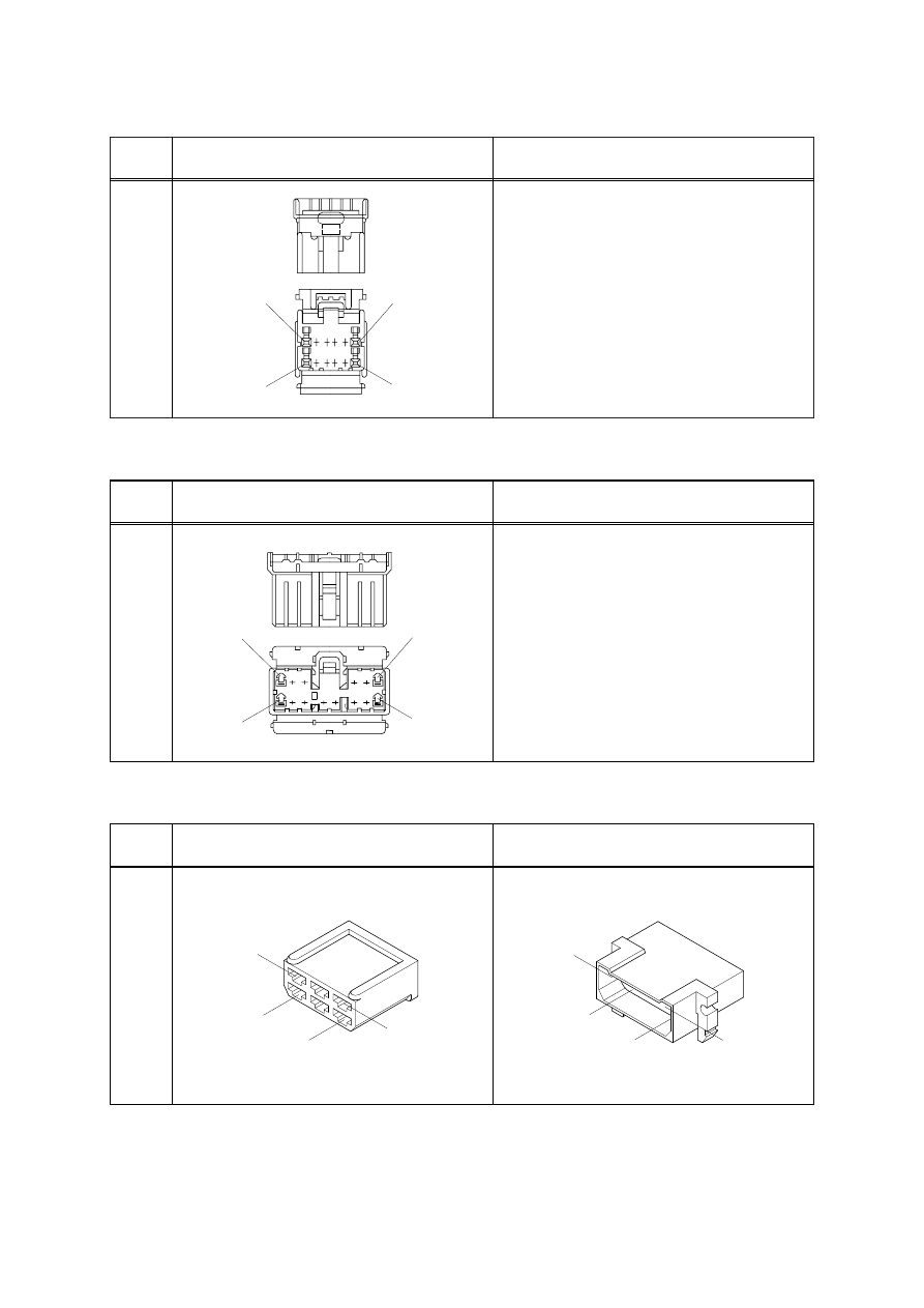
6
3
6
1
4
925276-0
1
4
3
6
480003-9
AMP FASTIN - FASTON CONNECTOR
10)