TC65i AT-Commands Set. Manual - part 5
12.2
AT+FCLASS Fax: Select, read or test service class
AT+FCLASS sets the ME to a particular mode of operation (data, fax). This allows the ME to process information
in a manner suitable for that type of information.
Syntax
Test Command
AT+FCLASS=?
Response(s)
(list of supported <n>s)
OK
Read Command
AT+FCLASS?
Response(s)
<n>
OK
Write Command
AT+FCLASS=<n>
Response(s)
OK
PIN ASC0 ASC1
USB MUX1
MUX2 MUX3 Charge
4
Last
Reference(s)
-
+
-
+
+
-
-
-
+
-
EIA/TIA-592-A
Parameter Description
<n>(num)(&W)(&V)
0(&F)
Data (e.g. EIA/TIA-602 or ITU V.250)
1
Fax class 1 (EIA/TIA-578-A, Service Class 1)
Notes
• Using Error Correcting Mode (ECM) when sending FAXes over GSM should be avoided.
• If <n> is set to 1, all incoming calls will be answered as fax calls when ATA is issued on multiplexer channel
1 resp. ASC0. For calls explicitly signaled as voice or data calls, this procedure will fail with result code "NO
CARRIER", but the incoming call will continue to ring.
It is possible to change the setting of <n> to 0 while the call is ringing, and accept the call afterwards with ATA.
12.3
AT+FRH Receive Data Using HDLC Framing
The AT+FRH command enables the TA to receive frames using the HDLC protocol and the modulation scheme
<mod>=3.
An ERROR response code results if the write command is issued while the modem is on-hook. The test com-
mand can be used either in on-hook or off-hook mode to check the value supported by the <mod> parameter.
Syntax
Test Command
AT+FRH=?
Response(s)
+FRH:(list of <mod>s)
OK
Write Command
AT+FRH=<mod>
Response(s)
CONNECT
If error is related to ME functionality
ERROR
PIN ASC0 ASC1
USB MUX1 MUX2 MUX3 Charge
4
Last
Reference(s)
-
+
-
+
+
-
-
-
-
-
TIA/EIA-578
Note
• TC65i supports only <mod>=3.
12.4
AT+FRM Receive Data
The AT+FRM command causes the TA to enter the receive mode, using one of the modulation schemes defined
in Section 12.1, FAX parameters.
An ERROR response code results if the write command is issued while the modem is on-hook. The test com-
mand can be used in on-hook or off-hook mode to check the modulation schemes supported by TC65i.
Syntax
Test Command
AT+FRM=?
Response(s)
(list of <mod>s)
OK
Write Command
AT+FRM=<mod>
Response(s)
CONNECT
If error is related to ME functionality:
ERROR
PIN ASC0 ASC1
USB MUX1 MUX2 MUX3 Charge
4
Last
Reference(s)
-
+
-
+
+
-
-
-
-
-
TIA/EIA-578
Note
•
<mod>= 3 is not possible.
12.5
AT+FRS Receive Silence
<time>=n causes the TA to report an OK result code to the TE after the specified period of silence was detected
on the line.
The command is aborted if any character is received by the TE. The modem discards the aborting character and
issues an OK result code. An ERROR response code results if this command is issued while the mode is on-
hook.
Syntax
Write Command
AT+FRS=<time>
Response(s)
OK
If error is related to ME functionality:
ERROR
PIN ASC0 ASC1
USB MUX1 MUX2 MUX3 Charge
4
Last
Reference(s)
-
+
-
+
+
-
-
-
-
-
TIA/EIA-578
Parameter Description
<time>(num)
Number of 10 millisecond intervals
0...255
12.6
AT+FTH Transmit Data Using HDLC Framing
The AT+FTH command causes the TA to transmit data using the HDLC protocol and the modulation scheme
<mod>=3.
An ERROR response code results if the write command is issued while the modem is on-hook. The test com-
mand can be used either in on-hook or off-hook mode to check the value supported by the <mod> parameter.
Syntax
Test Command
AT+FTH=?
Response(s)
+FTH:(list of <mod>s)
OK
Write Command
AT+FTH=<mod>
Response(s)
CONNECT
PIN ASC0 ASC1
USB MUX1 MUX2 MUX3 Charge
4
Last
Reference(s)
-
+
-
+
+
-
-
-
-
-
TIA/EIA-578
Note
• TC65i supports only <mod>=3.
12.7
AT+FTM Transmit Data
The AT+FTM command causes the TA to transmit data, using one of the modulation schemes defined in Section
12.1, FAX parameters.
An ERROR response code results if the write command is issued while the modem is on-hook. The test com-
mand can be used in on-hook or off-hook mode to check the modulation schemes supported by TC65i.
Syntax
Test Command
AT+FTM=?
Response(s)
(list of <mod>s)
OK
Write Command
AT+FTM=<mod>
Response(s)
CONNECT
If error is related to ME functionality:
ERROR
PIN ASC0 ASC1
USB MUX1 MUX2 MUX3 Charge
4
Last
Reference(s)
-
+
-
+
+
-
-
-
-
-
TIA/EIA-578
Note
•
<mod>= 3 is not possible
12.8
AT+FTS Stop Transmission and Wait
This command causes the TA to terminate a transmission and wait for <time> 10 millisecond intervals before
sending the OK result code to the TE.
Syntax
Write Command
AT+FTS=<time>
Response(s)
OK
In on-hook mode:
ERROR
PIN ASC0 ASC1
USB MUX1 MUX2 MUX3 Charge
4
Last
Reference(s)
-
+
-
+
+
-
-
-
-
-
TIA/EIA-578
Parameter Description
<time>(num)
no. of 10 millisecond intervals
0...85
13.
Short Message Service (SMS) Commands
The AT Commands described in this chapter allow an external application to use the Short Message Service with
the TC65i.
13.1
SMS parameters
Parameter Description
<ackpdu>(num)
Format is same for <pdu> in case of SMS, but without GSM 24.11 SC address field and parameter shall be
bounded by double quote characters like a normal string type parameter
<alpha>(str)(+CSCS)
String type alphanumeric representation of <da> or <oa> corresponding to the entry found in phonebook; this
feature is not supported
<cdata>(num)
Command Data
GSM 03.40 TP-Command-Data in text mode responses; ME/TA converts each 8-bit octet into two IRA character
long hexadecimal numbers (e.g. octet with integer value 42 is presented to TE as two characters 2A (IRA 50
and 65))
<ct>(num)
Command Type
GSM 03.40 TP-Command-Type in integer format
[0]...255
<da>(num)(+CSCS)
Destination Address
GSM 03.40 TP- Destination-Address Address-Value field in string format; BCD numbers (or GSM default alpha-
bet characters) are converted into characters; type of address given by <toda>
<data>(num)(+CSCS)
User Data
In case of SMS: GSM 03.40 TP-User-Data in text mode responses; format:
• If <dcs> indicates that GSM 03.38 default alphabet is used and <fo> indicates that GSM 03.40 TP-User-
Data-Header-Indication is not set: ME/TA converts GSM alphabet into current TE character set according to
rules covered in Annex A.
• If <dcs> indicates that 8-bit or UCS2 data coding scheme is used, or <fo> indicates that GSM 03.40 TP-
User-Data-Header-Indication is set: ME/TA converts each 8-bit octet into hexadecimal numbers con-taining
two IRA characters (e.g. octet with integer value 42 is presented to TE as two characters 2A (IRA 50 and 65).
In case of CBS: GSM 03.41 CBM Content of Message in text mode responses; format:
• If <dcs> indicates that GSM 03.38 default alphabet is used: ME/TA converts GSM alphabet into current TE
character set according to rules covered in Annex A.
• If <dcs> indicates that 8-bit or UCS2 data coding scheme is used: ME/TA converts each 8-bit octet into hexa-
decimal numbers containing two IRA characters.
<dt>(num)
Discharge Time
GSM 03.40 TP-Discharge-Time in time-string format: "yy/MM/dd,hh:mm:ss+zz", where characters indicate year
(two last digits), month, day, hour, minutes, seconds and time zone. For example, 6th of May 1994, 22:10:00
GMT+2 hours equals "94/05/06,22:10:00+08"
<ieia>(num)
IEIa (Information Element Identifier octet) of the concatenated SMS.
8
Concatenated short messages, 8-bit reference number
16
Concatenated short messages, 16-bit reference number
<index>(num)
Integer type; value in the range of location numbers supported by the associated memory
<length>(num)
Message Length
Integer type value indicating in the text mode (AT+CMGF=1) the length of the message body <data> (or
<cdata>) in characters; or in PDU mode (AT+CMGF=0), the length of the actual TP data unit in octets (i.e. the
RP layer SMSC address octets are not counted in the length) In text mode, the maximum length of an SMS
depends on the used coding scheme: It is 160 characters if the 7 bit GSM coding scheme is used, and 140 char-
acters according to the 8 bit GSM coding scheme.
If the SMS message format is ''text mode'' (AT+CMGF=1) and the character set is set to ''UCS2'' with AT+CSCS
and the SMS is also coded as "UCS2" (see <dcs> of AT+CSMP), then the length is in octets instead of charac-
ters.
For concatenated SMS messages the maximum length will be reduced by the length of the user data header
with respect to <ieia> (6 bytes for <ieia>=8 and 7 bytes for <ieia>=16). In the case of 8-bit data, the max-
imum length of the short message field is: 140 octets - (6 or 7) = 134 or 133. In the case of GSM 7 bit default
alphabet data, the maximum length of the short message is (140 - (6 or 7))*8/7 = 153 or 152 characters. In the
case of 16 bit UC2 data, the maximum length of the short message is: (140 - (6 or 7))/2)= 67 or 66 characters.
<max>(num)
Maximum number of all segments to be concatenated into one SMS, beginning with 1.
<max>=0 means: ignore the value. This will result in a non-concatenated SMS.
0...255
<mem1>(str)
Memory to be used when listing, reading and deleting messages:
“SM“
SIM message storage
“ME“
Mobile Equipment message storage
“MT“(D)
Sum of "SM" and "ME" storages
<mem2>(str)
Memory to be used when writing and sending messages:
“SM“
SIM message storage
“ME“
Mobile Equipment message storage
“MT“(D)
Sum of "SM" and "ME" storages
<mem3>(str)
Received messages will be placed in this memory storage if routing to TE is not set. See command AT+CNMI
with parameter <mt>=2.
“SM“
SIM message storage
“MT“(D)
Sum of "SM" and "ME" storages
<mid>(num)
Message Identifier
GSM 03.41 CBM Message Identifier in integer format
<mn>(num)
Message Number
GSM 03.40 TP-Message-Number in integer format
<mr>(num)
Message Reference
GSM 03.40 TP-Message-Reference in integer format
<oa>(num)(+CSCS)
Originating Address
GSM 03.40 TP-Originating-Address Address-Value field in string format; BCD numbers (or GSM default alpha-
bet characters) are converted into characters; type of address given by <tooa>
<page>(num)
Page Parameter
GSM 03.41 CBM Page Parameter bits 4-7 in integer format
<pages>(num)
Page Parameter
GSM 03.41 CBM Page Parameter bits 0-3 in integer format
<pdu>(num)
In the case of SMS: GSM 04.11 SC address followed by GSM 03.40 TPDU in hexadecimal format: ME/TA con-
verts each octet of TP data unit into hexadecimal numbers containing two IRA characters (e.g. octet with integer
value 42 is presented to TE as two characters 2A (IRA 50 and 65)). In the case of CBS: <ra> GSM 03.40 TP-
Recipient-Address Ad-dress-Value field in string format; BCD numbers (or GSM default alphabet characters)
are converted into characters; type of address given by <tora>
<ra>(num)(+CSCS)
Recipient Address
GSM 03.40 TP-Recipient-Address Address-Value field in string format; BCD numbers (or GSM default alphabet
characters) are converted to characters of the currently selected TE character set
(refer to command
AT+CSCS.); type of address given by <tora>
<ref>(num)
Reference number to identify all segments of the concatenated SMS (i.e. the number needs to be the same for
each segment). If <ieia>=8 then max=255, otherwise 65535.
0...255
0...65535
<sca>(num)(+CSCS)
Service Center Address
GSM 04.11 RP SC address Address-Value field in string format; BCD numbers (or GSM default alphabet char-
acters) are converted to characters of the currently selected TE character set (refer to command AT+CSCS); type
of address given by <tosca>
<scts>(num)
Service Centre Time Stamp
GSM 03.40 TP-Service-Centre-Time-Stamp in time-string format (refer <dt>)
<seq>(num)
Sequence number of the concatenated SMS beginning with 1. The number must be incremented by one for
each segment of the concatenated short message.
<seq>=0 means: ignore the value. This will result in a non-concatenated SMS.
0...255
<sn>(num)
Serial Number
GSM 03.41 CBM Serial Number in integer format
<st>(num)
Status
GSM 03.40 TP-Status in integer format
0...255
<stat>(str)
Message status
3GPP 27.005 Interface of SMS and CB. Indicates the status of message in memory.
Description
text mode (<mode>=1)
PDU mode (<mode>=0)
Default
Received unread mes-
"REC UNREAD"
0
for SMS reading com-
sages
mands
Received read messages
"REC READ"
1
Stored unsent messages
"STO UNSENT"
2
for SMS writing com-
mands
Stored sent messages
"STO SENT"
3
All messages
"ALL"
4
<toda>(num)
Type of Destination Address
GSM 04.11 TP-Destination-Address Type-of-Address octet in integer format (when first character of <da> is +
(IRA 43) default is 145, otherwise default is 129)
0...255
<tooa>(num)
Type of Originating Address
GSM 04.11 TP-Originating-Address Type-of-Address octet in integer format (default refer <toda>)
<tora>(num)
Type of Recipient Address
GSM 04.11 TP-Recipient-Address Type-of-Address octet in integer format (default refer <toda>)
<tosca>(num)
Type of Service Center Address
GSM 04.11 RP SC address Type-of-Address octet in integer format (default refer <toda>)
13.2
AT+CMGC Send an SMS command
Syntax
Test Command
AT+CMGC=?
Response(s)
OK
Write Command
If text mode (see AT+CMGF=1)
AT+CMGC=<fo>, <ct>[, <pid>[, <mn>[, <da>[, <toda>]]]]<CR> Text can be entered <CTRL-Z>/<ESC>
Response(s)
+CMGC: <mr>[, <scts>]
If sending fails
ERROR
+CMS ERROR: <err>
Write Command
If PDU mode (see AT+CMGF=0)
AT+CMGC=<length><CR> PDU can be entered <CTRL-Z>/<ESC>
Response(s)
+CMGC: <mr>[, <ackpdu>]
OK
If sending fails
ERROR
+CMS ERROR: <err>
PIN ASC0 ASC1
USB MUX1 MUX2 MUX3 Charge
4
Last
Reference(s)
+
+
+
+
+
+
+
-
-
-
GSM 07.05
Notes
• After invoking the commands AT+CMGW, AT+CMGS or AT+CMGC it is necessary to wait for the prompt ">"
before entering text or PDU. After the prompt a timer will be started to observe the input.
• At baudrates below 19200 it is recommended to use the line termination character only (refer to ATS3, default
<CR>) before entering the text or PDU. Use of the line termination character followed by the response format-
ting character (refer to ATS4, default <LF> can cause problems
13.3
AT+CMGD Delete short message
The write command deletes a short message from the preferred message storage <mem1> location <index>.
Syntax
Test Command
AT+CMGD=?
Response(s)
OK
Write Command
AT+CMGD=<index>
Response(s)
OK
ERROR
+CMS ERROR: <err>
PIN ASC0 ASC1
USB MUX1 MUX2 MUX3 Charge
4
Last
Reference(s)
+
+
+
+
+
+
+
-
+
-
GSM 07.05
Notes
• If there is no short message stored at the selected index, the response is OK too.
• Users should be aware that when using this AT command quickly after SIM PIN authentication the SIM data
may not yet be accessible, resulting in a short delay before the requested AT command response is returned.
See Section 23.1, Restricted access to SIM data after SIM PIN authentication for further detail.
13.4
AT+CMGF Select SMS message format
Syntax
Test Command
AT+CMGF=?
Response(s)
+CMGF: (list of supported<mode>s)
OK
Read Command
AT+CMGF?
Response(s)
+CMGF: <mode>
OK
Write Command
AT+CMGF=<mode>
Response(s)
OK
PIN ASC0 ASC1
USB MUX1 MUX2 MUX3 Charge
4
Last
Reference(s)
-
+
+
+
+
+
+
-
+
-
GSM 07.05
Command Description
The write command specifies the input and output format of the short messages.
Parameter Description
<mode>(num)(&W)(&V)
[0](&F)
PDU mode
1
Text mode
13.5
AT+CMGL List SMS messages from preferred store
The write command returns messages with status value <stat> from message storage <mem1> to the TE. If the
status of the message is 'received unread', the status in the storage changes to 'received read'.
The execute command is the same as the write command with the given default for <stat>.
Syntax
Test Command
AT+CMGL=?
Response(s)
+CMGL: (list of supported <stat>s)
OK
Exec Command
AT+CMGL
Response(s)
+CMGL: (see write command for default of <stat>)
OK
Write Command
AT+CMGL=<stat>
Response(s)
Output if text mode (AT+CMGF=1) and command successful:
For SMS- SUBMITs and/or SMS-DELIVERs
+CMGL: <index>, <stat>, <oa>/<da>, [<alpha>], [<scts>][, <tooa>/<toda>, <length>]
<data>
[... ]
OK
For SMS-STATUS-REPORTs
+CMGL: <index>, <stat>, <fo>, <mr>, [<ra>], [<tora>], <scts>, <dt>, <st>
[... ]
OK
For SMS-Commands
+CMGL: <index>, <stat>, <fo>, <ct>
[... ]
OK
Output if PDU mode AT+CMGF=0 and command successful:
For SMS-SUBMITs and/or SMS-DELIVERs
+CMGL: <index>, <stat>, [<alpha>], <length>
<pdu>
[... ]
OK
If error is related to ME functionality
ERROR
+CMS ERROR: <err>
PIN ASC0 ASC1
USB MUX1 MUX2 MUX3 Charge
4
Last
Reference(s)
+
+
+
+
+
+
+
-
+
-
GSM 07.05
Notes
• The selected <mem1> can contain different types of SMs (e.g. SMS-DELIVERs, SMS-SUBMITs, SMS-STA-
TUS-REPORTs and SMS-COMMANDs), the response may be a mix of the responses of different SM types.
TE application can recognize the response format by examining the third response parameter.
• The parameters <ra> and <tora> will only be displayed if parameter <ra> of the AT^SSCONF command is
set to 1.
• Users should be aware that when using this AT command quickly after SIM PIN authentication the SIM data
may not yet be accessible, resulting in a short delay before the requested AT command response is returned.
See Section 23.1, Restricted access to SIM data after SIM PIN authentication for further detail.
• If the ME is Java controlled, take into account that the AT Command API can handle responses up to a length
of 1024 bytes. To avoid any longer reponses it is recommended not to read the entire range of phonebook
entries at a time.
13.6
AT+CMGR Read SMS messages
The write command returns SMS message with location value <index> from message storage <mem1> to the
TE. If status of the message is 'received unread', status in the storage changes to 'received read'.
Syntax
Test Command
AT+CMGR=?
Response(s)
OK
Write Command
AT+CMGR=<index>
Response(s)
Output if text mode (AT+CMGF=1) and command successful:
For SMS-DELIVER
+CMGR: <stat>, <oa>, [<alpha>], <scts>[, <tooa>, <fo>, <pid>, <dcs>, <sca>, <tosca>,
<length>]
<data>
[... ]
OK
For SMS-SUBMIT
+CMGR: <stat>, <da>, [<alpha>][, <toda>, <fo>, <pid>, <dcs>, [<vp>], <sca>, <tosca>, <length>]
<data>
[... ]
OK
For SMS-STATUS-REPORT
+CMGR: <stat>, <fo>, <mr>, [<ra>], [<tora>], <scts>, <dt>, <st>
<data>
[... ]
OK
For SMS-Commands
+CMGR: <stat>, <fo>, <ct>[, <pid>, [<mn>], [<da>], [<toda>], <length>]
<data>
[... ]
OK
Output if PDU mode (AT+CMGF=0) and command successful:
For SMS-SUBMITs and/or SMS-DELIVERs
+CMGR: <stat>, [<alpha>], <length>
<pdu>
[... ]
OK
ERROR
+CMS ERROR: <err>
PIN ASC0 ASC1
USB MUX1 MUX2 MUX3 Charge
4
Last
Reference(s)
+
+
+
+
+
+
+
-
+
-
GSM 07.05
Notes
• Response if AT+CMGR is used to read an empty record index: +CMGR: 0,,0
• Response if AT+CMGR is used to read a non-existent record index: +CMS ERROR: invalid memory index
• The parameters <ra> and <tora> will only be displayed if parameter <ra> of the AT^SSCONF command is
set to 1.
• Users should be aware that when using this AT command quickly after SIM PIN authentication the SIM data
may not yet be accessible, resulting in a short delay before the requested AT command response is returned.
See Section 23.1, Restricted access to SIM data after SIM PIN authentication for further detail.
13.7
AT+CMGS Send Short Message
The write command transmits a short message from TE to network (SMS-SUBMIT).
After invoking the write command wait for the prompt ">" and then start to write the message. To send the mes-
sage simply enter <CTRL-Z>. After the prompt a timer will be started to observe the input.
To abort sending use <ESC>. Abortion is acknowledged with "OK", though the message will not be sent.
The message reference <mr> is returned to the TE on successful message delivery. The value can be used to
identify the message in a delivery status report provided as an unsolicited result code.
Syntax
Test Command
AT+CMGS=?
Response(s)
OK
Write Command
If text mode (see AT+CMGF=1)
AT+CMGS=<da>[, <toda>]<CR> Text can be entered. <CTRL-Z>/<ESC>
Response(s)
+CMGS: <mr>[, <scts>]
OK
If sending fails see notes below.
Write Command
If PDU mode (see AT+CMGF=0)
AT+CMGS=<length><CR> PDU can be entered. <CTRL-Z>/<ESC>
Response(s)
+CMGS: <mr>[, <ackpdu>]
OK
If sending fails see notes below.
PIN ASC0 ASC1
USB MUX1 MUX2 MUX3 Charge
4
Last
Reference(s)
+
+
+
+
+
+
+
-
-
-
GSM 07.05
Notes
• If sending fails, for example, if a message is too long, the result code depends on the current setting of the
AT^SM20 command:
If the AT^SM20 <CmgwMode> equals 1 (factory default) any failure to send a message is responded with "OK".
Users should be aware, that despite the "OK" response, the message will not be sent to the subscriber.
If the AT^SM20 <CmgwMode> equals 0 any failure to send a message is responded with "ERROR".
• If sending fails due to timeout, then
AT^SM20 <CmgwMode>=1 causes "+CMS ERROR: unknown error" to be returned;
AT^SM20 <CmgwMode>=0 causes "+CMS ERROR: timer expired" to be returned.
• Note that some providers do not recognize an @ symbol used in a short message. A widely used alternative
is typing "*" as defined in GSM 03.40 (GPP TS 23.40).
• All characters entered behind the prompt ">" will be recognized as GSM characters. For example, "Back-
space" (ASCII character 8) does not delete a character, but will be inserted into the short message as an addi-
tional physical character. As a result, the character you wanted to delete still appears in the text, plus the GSM
code equivalent of the Backspace key.
• Message Length in Text Mode
The maximum length of a short message depends on the used coding scheme: It is 160 characters if the 7
bit GSM coding scheme is used, and 140 characters according to the 8 bit GSM coding scheme.
In case UCS2 character set selected it is highly recommended to set Data Coding Scheme (<dcs> of
AT+CSMP) to 16-bit data, otherwise the length of sms user data is restricted to 88 octets. Even better for mes-
sages with UCS2 character set is the PDU Mode.
• At baudrates lower than 19200 it is recommended to use the line termination character only (refer to <n> of
ATS3, default <CR>) before entering text or PDU. Use of the line termination character followed by the
response formatting character (see <n> of ATS4, default <LF>) can cause problems.
• During a pending USSD user interaction the AT+CMGS write command returns "+CME ERROR: operation
temporary not allowed" to prevent blocking situations.
13.8
AT+CMGW Write Short Messages to Memory
The execute and write commands transmit a short message (either SMS-DELIVER or SMS-SUBMIT) from TE
to memory storage <mem2>. Memory location <index> of the stored message is returned. Message status will
be set to 'stored unsent' unless otherwise given in parameter <stat>.
After invoking the execute or write command wait for the prompt ">" and then start to write the message. To save
the message simply enter <CTRL-Z>. After the prompt a timer will be started to observe the input.
To abort writing use <ESC>. Abortion is acknowledged with "OK", though the message will not be saved.
Syntax
Test Command
AT+CMGW=?
Response(s)
OK
Exec Command
If text mode (see AT+CMGF=1):
AT+CMGW
Response(s)
<CR> Text can be entered. <CTRL-Z>/<ESC>
+CMGW: <index>
OK
If writing fails
ERROR
+CMS ERROR: <err>
Write Command
If text mode (see AT+CMGF=1):
AT+CMGW=<oa>/<da>[, [<tooa>/<toda>][, <stat>]]<CR> Text can be entered. <CTRL-Z>/<ESC>
Response(s)
+CMGW: <index>
OK
If writing fails see notes below.
Write Command
If PDU mode (see AT+CMGF=0):
AT+CMGW=<length>[, <stat>]<CR> PDU can be entered. <CTRL-Z>/<ESC>
Response(s)
+CMGW: <index>
OK
If writing fails see notes below.
PIN ASC0 ASC1
USB MUX1 MUX2 MUX3 Charge
4
Last
Reference(s)
+
+
+
+
+
+
+
-
+
-
GSM 07.05
Notes
• If writing fails, for example, if a message is too long, the result code depends on the current setting of the
AT^SM20 command:
If the AT^SM20 <CmgwMode>=1 (factory default) any failure to send a message is responded with "OK". Users
should be aware, that despite the "OK" response, the message will not be written to the selected SMS stor-
age.
If the AT^SM20 <CmgwMode> equals 0 any failure to write a message is responded with "ERROR".
• If writing fails due to timeout, then
AT^SM20 <CmgwMode>=1 causes "+CMS ERROR: unknown error" to be returned;
AT^SM20 <CmgwMode>=0 causes "+CMS ERROR: timer expired" to be returned.
• Note that some providers do not recognize an @ symbol used in a short message. A widely used alternative
is typing "*" as defined in GSM 03.40 (GPP TS 23.40).
• For baudrates lower than 19200 it is recommended to use the line termination character only (refer to ATS3=
<n>, default <CR>) before entering the text or PDU. Use of the line termination character followed by the
response formating character (see ATS4= <n>, default <LF>) may cause problems.
• SMS-COMMANDs and SMS-STATUS-REPORTs cannot be stored in text mode.
• All characters entered behind the ">" prompt will be recognized as GSM characters. For example, "Back-
space" (ASCII character 8) does not delete a character, but will be inserted into the short message as an addi-
tional physical character. As a result, the character you wanted to delete still appears in the text, plus the GSM
code equivalent of the Backspace key.
• Message Length in Text Mode
The maximum length of a short message depends on the used coding scheme: It is 160 characters if the 7
bit GSM coding scheme is used, and 140 characters according to the 8 bit GSM coding scheme.
In case UCS2 character set selected it is highly recommended to set Data Coding Scheme (<dcs> of
AT+CSMP) to 16-bit data, otherwise the length of sms user data is restricted to 88 octets. Even better for mes-
sages with UCS2 character set is the PDU Mode.
• The length of 8-bit data coded short messages has to be greater than 0.
13.9
AT+CMSS Send short messages from storage
The write command sends message with location value <index> from message storage <mem2> to the network
(SMS-SUBMIT or SMS-COMMAND). If new recipient address <da> is given for SMS-SUBMIT, it shall be used
instead of the one stored with the message. Reference value <mr> is returned to the TE on successful message
delivery. Value can be used to identify message upon unsolicited delivery status report result code.
If the optional parameter <da> is given, the old status of the short message at <index> remains unchanged
(see <stat>).
Syntax
Test Command
AT+CMSS=?
Response(s)
OK
Write Command
If text mode (AT+CMGF=1):
AT+CMSS=<index>[, <da>[, <toda>]]
Response(s)
+CMSS: <mr>[, <scts>]
OK
If sending fails
ERROR
+CMS ERROR: <err>
Write Command
If PDU mode (AT+CMGF=0):
AT+CMSS=<index>[, <da>[, <toda>]]
Response(s)
+CMSS: <mr>[, <ackpdu>]
OK
If sending fails
ERROR
+CMS ERROR: <err>
PIN ASC0 ASC1
USB MUX1 MUX2 MUX3
Charge
4
Last
Reference(s)
+
+
+
+
+
+
+
-
-
-
GSM 07.05
13.10
AT+CNMA New Message Acknowledgement to ME/TE, only
phase 2+
The write / execute command confirms successful receipt of a new message (SMS-DELIVER or SMS-STATUS-
REPORT) routed directly to the TE. TA shall not send another +CMT or +CDS result code to TE until previous
one is acknowledged. If ME does not receive acknowledgement within required time (network time-out), ME
sends RP-ERROR to the network. TA shall automatically disable routing to TE by setting both <mt> and <ds>
values of AT+CNMI to zero.
Syntax
Test Command
AT+CNMA=?
Response(s)
+CNMA: (list of supported <n>s)
OK
Exec Command
AT+CNMA
Response(s)
OK
ERROR
+CMS ERROR: <err>
Write Command
AT+CNMA=<n>
Response(s)
OK
ERROR
+CMS ERROR: <err>
PIN ASC0 ASC1
USB MUX1 MUX2
MUX3
Charge
4
Last
Reference(s)
+
+
+
+
+
+
+
-
-
-
GSM 07.05
Parameter Description
<n>(num)
Parameter required only for PDU mode.
0
Command operates similarly as in text mode.
Notes
• The execute / write command shall only be used when AT+CSMS parameter <service> equals 1 (= phase
2+).
• The execute command can be used no matter whether text mode or PDU mode is activated. The write com-
mand is designed for the PDU mode only.
• If multiplex mode is activated (AT+CMUX=0) the AT+CNMI parameter will be set to zero on all channels, if one
channel fails to acknowledge an incoming message within the required time.
13.11
AT+CNMI New short Message Indication
The write command selects the procedure how the receipt of new short messages from the network is indicated
to the TE when TE is active, e.g. DTR signal is ON. If TE is inactive (e.g. DTR signal is OFF), message receiving
should be done as specified in GSM 03.38. If the DTR signal is not available or the state of the signal is ignored
(V.250 command AT&D0, reliable message transfer can be assured by using AT+CNMA acknowledgment proce-
dure. The rules <mt>=2 and <mt>=3 for storing received messages are possible only if phase 2+ compatibility
is activated with AT+CSMS=1. The parameter <ds>=1 is only available in phase 2+
Syntax
Test Command
AT+CNMI=?
Response(s)
+CNMI: (list of supported<mode>s), (list of supported <mt>s), (list of supported <bm>s), (list of supported
<ds>s), (list of supported <bfr>s)
OK
Read Command
AT+CNMI?
Response(s)
+CNMI: <mode>, <mt>, <bm>, <ds>, <bfr>
OK
Write Command
AT+CNMI=<mode>[, <mt>[, <bm>[, <ds>[, <bfr>]]]]
Response(s)
OK
ERROR
+CMS ERROR: <err>
PIN ASC0 ASC1
USB MUX1 MUX2 MUX3 Charge
4
Last
Reference(s)
+
+
+
+
+
+
+
-
+
-
GSM 07.05
Unsolicited Result Codes
URC 1
<mt>=1:
+CMTI: <mem3>, <index>
Indicates that new message has been received
URC 2
<mt>=2 (PDU mode enabled):
+CMT: <length><CR><LF><pdu>
Indicates that new message has been received
URC 3
<mt>=2 (text mode enabled):
+CMT: <oa>, <scts>[, <tooa>, <fo>, <pid>, <dcs>, <sca>, <tosca>,
<length>]<CR><LF><data>
Indicates that new message has been received
URC 4
<bm>=2 (PDU mode enabled):
+CBM: <length><CR><LF><pdu>
Indicates that new cell broadcast message has been received
URC 5
<bm>=2 (text mode enabled):
+CBM: <sn>, <mid>, <dcs>, <page>, <pages><CR><LF><data>
Indicates that new cell broadcast message has been received
URC 6
<ds>=1 (PDU mode enabled):
+CDS: <length><CR><LF><pdu>
Indicates that new SMS status report has been received
URC 7
<ds>=1 (text mode enabled):
+CDS: <fo>, <mr>[, <ra>][, <tora>], <scts>, <dt>, <st>
Indicates that new SMS status report has been received
URC 8
<ds>=2:
+CDSI: <mem3>, <index>
Indicates that new SMS status report has been received
Parameter Description
<mode>(num)(&W)
[0](&F)
Buffer unsolicited result codes in the TA. If TA result code buffer is full, indica-
tions can be buffered in some other place or the oldest indications may be dis-
carded and replaced with the new received indications.
1
Discard indication and reject new received message unsolicited result codes
when TA-TE link is reserved (e.g. in on-line data mode). Otherwise forward
them directly to the TE.
2
Buffer unsolicited result codes in the TA when TA-TE link is reserved (e.g. in
online data mode) and flush them to the TE after reservation. Otherwise for-
ward them directly to the TE.
3
Forward unsolicited result codes directly to the TE. When TA-TE link is
reserved (e.g. in online data mode) the URCs are signaled according to the
AT^SCFG parameters <uri>, <udri> and <urat>
<mt>(num)(&W)(&V)
Rules for storing received short messages depend on the relevant data coding method (refer to GSM 03.38),
preferred memory storage (AT+CPMS) setting and this value.
Note: If AT command interface is acting as the only display device, the ME must support storage of class 0 mes-
sages and messages in the message waiting indication group (discard message)
[0](&F)
No SMS-DELIVER indications are routed to the TE.
1
If SMS-DELIVER is stored in ME/TA, indication of the memory location is
routed to the TE using unsolicited result code.
2
SMS-DELIVERs, except class 2 messages and messages in the message
waiting indication group (store message) are routed directly to the TE using
unsolicited result code.
3
Class 3 SMS-DELIVERs are routed directly to the TE using unsolicited result
codes defined in <mt>=2. Messages of other data coding schemes result in
indication as defined in <mt>=1.
<bm>(num)(&W)(&V)
Rules for storing received CBMs depend on the relevant data coding method (refer to GSM 03.38), the setting
of Select CBM Types (AT+CSCB) and this value:
[0](&F)
No CBM indications are routed to the TE.
2
New CBMs are routed directly to the TE using unsolicited result code.
3
Class 3 CBMs are routed directly to TE using unsolicited result codes defined
in <bm>=2.
<ds>(num)(&W)(&V)
[0](&F)
No SMS-STATUS-REPORTs are routed to the TE.
1
SMS-STATUS-REPORTs are routed to the TE using unsolicited result code.
2
If SMS-STATUS-REPORT is routed into ME/TA, indication of the memory
location is routed to the TE using unsolicited result code.
<bfr>(num)(&V)
[1](&F)
TA buffer of unsolicited result codes defined within this command is cleared
when <mode> changes from 0 to 1...3.
<index>(num)
Integer type; value in the range of location numbers supported by the associated memory
Notes
• Parameters <mt>=2,3 and <ds>=1 are only available with GSM phase 2+ (see AT+CSMS=1). Incoming SMs
or Status Reports have to be acknowledged with AT+CNMA=0 when using these phase 2+ parameters.
• Requirements specific to Multiplex mode:
In multiplex mode (AT+CMUX=0) only one channel can use a phase 2+ parameter. The parameter for <mt>
and <ds> on the other channels have to be set to zero. If either a SM or a Status Report is not acknowledged,
all AT+CNMI parameter in all channels will be set to zero.
• If the ME operates on different instances (MUX channels 1, 2, 3 or ASC0/ASC1) avoid different settings for
routing and indicating short messages. For example, if messages shall be routed directly to one instance of
the TE (set with AT+CNMI, AT^SSDA), it is not possible to activate the presentation of URCs with AT+CMER
or AT+CNMI on another instance. Any attempt to activate settings that conflict with existing settings on
another interface, will result in "+CME ERROR", or accordingly "+CMS ERROR".
• Handling of Class 0 short messages:
If the host application is provided with a display and AT^SSDA=1 has been set Class 0 short messages can
be displayed immediately.
If the host application does not include a display, ME handles Class 0 short messages as though there was
no message class, i.e. it will ignore bits 0 and 1 in the <dcs> and normal rules for exceeded memory capacity
shall apply. This approach is compliant with GSM 03.38 .
• The parameters <ra> and <tora> will only be displayed if <ra> of the AT^SSCONF command is set to 1.
• If either a SM or a Status Report is not acknowledged, all AT+CNMI parameter in all channels will be set to
zero.
13.12
AT+CPMS Preferred SMS message storage
The write command selects memory storages <mem1>,<mem2>, <mem3> to be used for reading, writing, etc.
Syntax
Test Command
AT+CPMS=?
Response(s)
+CPMS: (list of supported <mem1>s), (list of supported <mem2>s), (list of supported <mem3>s)
OK
Read Command
AT+CPMS?
Response(s)
+CPMS: <mem1>, <used1>, <total1>, <mem2>, <used2>, <total2>, <mem3>, <used3>, <total3>
OK
ERROR
+CMS ERROR: <err>
Write Command
AT+CPMS=<mem1>[, <mem2>[, <mem3>]]
Response(s)
+CPMS: <used1>, <total1>, <used2>, <total2>, <used3>, <total3>
OK
ERROR
+CMS ERROR: <err>
PIN ASC0 ASC1
USB MUX1 MUX2 MUX3 Charge
4
Last
Reference(s)
+
+
+
+
+
+
+
-
+
-
GSM
07.05
Parameter Description
<used1>(num)
Number of messages currently in <mem1>
<used2>(num)
Number of messages currently in <mem2>
<used3>(num)
Number of messages currently in <mem3>
<total1>(num)
Number of messages storable in <mem1>
<total2>(num)
Number of messages storable in <mem2>
<total3>(num)
Number of messages storable in <mem3>
Notes
•
The Mobile Equipment storage ''ME'' offers space for 25 short messages, see <mem1>.
•
''MT'' is the sum of ''ME'' (= 25 locations) and ''SM'' (capacity varies with SIM card). The indices <index> of
the ''MT'' storage are dependent on the order selected with AT^SSMSS
•
The <mem1>, <mem2> and <mem3> parameter will be stored in non-volatile memory.
•
The user should be aware that the setting ''MT'' involves ''ME'' and ''SM'', with ''ME'' being filled up first. If the
''ME'' storage is full, TC65i will proceed with the ''SM'' storage.
Incoming Class 1 short messages (ME specific) will be preferably stored to ''ME'' and may be transferred to
the ''SM'' storage if ''ME'' is used up.
Incoming Class 2 messages (SIM specific) will be stored to the SIM card only, no matter whether or not there
is free ''ME'' space. As a result, the ^SMGO: 2 indication (see AT^SMGO) may be presented without prior indi-
cation of ^SMGO: 1. For more information regarding SIM and ME specific message classes refer to <dcs>
and the following specifications: GSM 03.38 and 3GPP TS23038.
•
Multiplexer: In Multiplex mode or when the two physical serial interfaces are connected, the parameter
<mem3> will be the same on all instances, but the settings of <mem1> and <mem2> may vary on each channel
/ interface. As a result, changes on parameter <mem1> and/or <mem2> befor activating the multiplexer or dif-
ferences values for other instanes can result in not desired behaviours like different outputs for AT+CMGL and
so on.
•
While <mem3> equals ''SM'' and <mem1> equals ''ME'' it is possible that, after deleting short messages from
''ME'', the freed space on ''ME'' is reclaimed for new incoming short messages, when there is no space left on
the ''SM'' storage. As it is often the clients concern to have received short messages stored only to the SIM
card, inconsistent settings should be generally avoided. This can be achieved simply by using the same
parameter for all memory indices.
•
Users should be aware that when using this AT command quickly after SIM PIN authentication the SIM data
may not yet be accessible, resulting in a short delay before the requested AT command response is returned.
See Section 23.1, Restricted access to SIM data after SIM PIN authentication for further detail.
•
The indices <index> of the storage are dependent on the order selected with AT^SSMSS.
13.13
AT+CSCA SMS Service Center Address
Write command updates the SMSC address, through which mobile originated SMs are transmitted. In text mode,
setting is used by send and write commands. In PDU mode, setting is used by the same commands, but only
when the length of the SMSC address coded into the <pdu> parameter equals zero.
Syntax
Test Command
AT+CSCA=?
Response(s)
OK
Read Command
AT+CSCA?
Response(s)
+CSCA: <sca>, <tosca>
OK
Write Command
AT+CSCA=<sca>[, <tosca>]
Response(s)
OK
PIN ASC0 ASC1
USB MUX1 MUX2 MUX3 Charge
4
Last
Reference(s)
+
+
+
+
+
+
+
-
+
-
GSM 07.05
Notes
• In case of using no parameter after AT+CSCA= the content of <sca> will be deleted.
• This command writes the service center address to non-volatile memo.
• The SMS service center address should be entered as specified by the service provider.
13.14
AT+CSCB Select Cell Broadcast Message Indication
The test command returns the supported modes as a compound value.
The write command selects which types of CBMs are to be received by the ME.
Syntax
Test Command
AT+CSCB=?
Response(s)
+CSCB: (list of supported <mode>s)
OK
Read Command
AT+CSCB?
Response(s)
+CSCB: <mode>, <mids>, <dcss>
OK
Write Command
AT+CSCB=<mode>[, <mids>[, <dcss>]]
Response(s)
OK
PIN ASC0 ASC1
USB MUX1 MUX2 MUX3 Charge
4
Last
Reference(s)
+
+
+
+
+
+
+
-
+
-
GSM 07.05
Parameter Description
<mode>(num)
Message mode
0(&F)
Accept messages that are defined in <mids> and <dcss>
1
Forbid messages that are defined in <mids> and <dcss>
<mids>(str)
Cell Broadcast Message ID specification
[““](&F)
default value of this parameter is empty string, and it means that no CBM iden-
tifiers are specified.
• For <mode>=0: Six different possible combinations of CBM IDs (e.g. "0,1,5,320-478,922,2000-3000").
In certain configurations, e.g. if using SIMs that contain data in Elementary File EF-CBMID (Cell Broadcast
Message Identifier for Data download) less than six combinations may be available.
To access a SIM's Elementary File data refer to command AT+CRSM.
• For <mode>=1: One CBM ID or range of IDs (e.g. "320-478").
<dcss>(str)
CBM data coding scheme specification
[““](&F)
default value of this parameter is empty string
All different possible combinations of CBM data coding schemes (e.g. "0-3,5"). Using default empty string leads
to get all CBMs independent of their dcss.
A given <dcss> replaces any former value and is used for consecutive requests.
13.15
AT+CSDH Show SMS text mode parameters
The write command sets whether or not detailed header information is shown in text mode result codes.
Syntax
Test Command
AT+CSDH=?
Response(s)
+CSDH: ((list of supported <show>s)
OK
Read Command
AT+CSDH?
Response(s)
+CSDH:<show>
OK
Write Command
AT+CSDH=<show>
Response(s)
+CSDH: <show>
OK
PIN ASC0 ASC1
USB MUX1
MUX2 MUX3 Charge
4
Last
Reference(s)
+
+
+
+
+
+
+
-
+
-
GSM 07.05
Parameter Description
<show>(num)(&W)
[0](&F)
Do not show header values defined in commands AT+CSCA and AT+CSMP
(<sca>, <tosca>,<fo>,<vp>, <pid> and <dcs>) nor <length>, <toda> or
<tooa> in "+CMTI", AT+CMGL, AT+CMGR result codes for SMS-DELIVERs and
SMS-SUBMITs in text mode; for SMS-COMMANDs in +CMGR result code, do
not show <pid>,<mn>,<da>, <toda>, <length> or <cdata>
1
Show the values in result codes
13.16
AT+CSMP Set SMS text Mode Parameters
The write command selects values for additional parameters needed when the short message is sent to the net-
work or placed in a storage when text format message mode is selected.
It is possible to set the validity period starting from the time when the short message is received by the SMSC
(<vp> is in range 0... 255) or define the absolute time of the validity period termination (<vp> is a string). The
format of <vp> is given by <fo>. If TA supports the enhanced validity period format, see GSM
03.40), it shall be
given as a hexadecimal coded string (e.g. <pdu>) with quotes.
Syntax
Test Command
AT+CSMP=?
Response(s)
OK
Read Command
AT+CSMP?
Response(s)
+CSMP:<fo>, <vp>/ <scts>, <pid>, <dcs>
OK
Write Command
AT+CSMP=<fo>[, <vp>/<scts>[, <pid>[, <dcs>]]]
Response(s)
+CSMP: <index>
OK
If sending fails
ERROR
+CMS ERROR: <err>
PIN ASC0 ASC1
USB MUX1 MUX2 MUX3 Charge
4
Last
Reference(s)
+
+
+
+
+
+
+
-
+
-
GSM 07.05
Parameter Description
<fo>(num)
First Octet
depending on the command or result code: first octet of GSM
03.40 SMS-DELIVER, SMS-SUBMIT (default 17),
SMS-STATUS-REPORT, or SMS-COMMAND (default 2) in integer format
0...17(&F)...255
<vp>(num)
Depending on SMS-SUBMIT <fo> setting: GSM 03.40 TP-Validity-Period either in integer format or in time-
string format (refer <dt>)
0...167(&F)...255
<dcs>(num)
Data Coding Scheme
GSM 03.38 SMS Data Coding Scheme, or Cell Broadcast Data Coding Scheme in integer format
0(&F)...247
<pid>(num)
Protocol Identifier
GSM 03.40 TP-Protocol-Identifier in integer format
0(&F)...255
Notes
• When storing a SMS DELIVER from the TE to the preferred memory storage in text mode (using the AT+CMGW
write command), <vp> field can be used for <scts>.
• The command writes the parameters to the non-volatile memory.
13.17
AT+CSMS Select Message Service
Syntax
Test Command
AT+CSMS=?
Response(s)
+CSMS: (list of supported<service>s)
OK
Read Command
AT+CSMS?
Response(s)
+CSMS: <service>, <mt>, <mo>, <bm>
OK
Write Command
AT+CSMS=<service>
Response(s)
+CSMS: <mt>, <mo>, <bm>
OK
ERROR
+CMS ERROR: <err>
PIN ASC0 ASC1
USB MUX1 MUX2 MUX3
Charge
4
Last
Reference(s)
+
+
+
+
+
+
+
-
+
-
GSM 07.05
Parameter Description
<service>(num)(&W)(&V)
0(&F)
GSM 03.40 and GSM
03.41 (the syntax of SMS AT commands is compatible
with GSM 07.05 Phase 2 version 4.7.0; Phase 2+ features which do not require
new command syntax may be supported, e.g. correct routing of messages with
new Phase 2+ data coding schemes)
1
GSM 03.40 and GSM 03.41 (the syntax of SMS AT commands is compatible
with GSM 07.05 Phase 2+ version; the requirement of <service> setting 1 is
mentioned under corresponding command descriptions).
<mt>(num)
Mobile Terminated Messages:
0
Type not supported
1
Type supported
<mo>(num)
Mobile Originated Messages:
0
Type not supported
1
Type supported
<bm>(num)
Broadcast Type Messages:
0
Type not supported
1
Type supported
Notes
• If CSMS mode is switched from Phase 2+ to Phase 2 and one or more AT+CNMI Parameter are Phase 2+
specific a "+CMS ERROR: unknown error" will appear. It is recommended to switch the AT+CNMI Parameters
to Phase 2 specific values before entering Phase 2.
• Phase 2+ (<service>=1) must be set before the following features can be used:
- Configuring procedures for indicating received short messages with the AT+CNMI parameters <mt>=2 or
<mt>=3 and <ds>=1.
- Acknowledging incoming short messages with AT+CNMA.
- Receiving Status Reports and acknowledging them with AT+CNMA.
13.18
AT^SCML List Concatenated Short Messages from preferred
store
The write command returns messages with status value <stat> from message storage <mem1> to the TE. If
the status of the message is 'received unread', the status in the storage changes to 'received read'. The execute
command is the same as the write command with the given default for <stat>. See notes of AT+CMGL.
Syntax
Test Command
AT^SCML=?
Response(s)
^SCML: (list of supported <stat>s)
OK
Exec Command
AT^SCML
Response(s)
^SCML: (see write command for default of <stat>)
OK
Write Command
AT^SCML=<stat>
Response(s)
Output if text mode (AT+CMGF=1) and command successful:
For SMS-SUBMITs and/or SMS-DELIVERs
^SCML: <index>, <stat>, <oa>/<da>, [<alpha>], [<scts>][, <tooa>/<toda>, <length>][, <seq>,
<max>, <ieia>, <ref>]
<data>
[... ]
OK
For SMS-STATUS-REPORTs
^SCML: <index>, <stat>, <fo>, <mr>, [<ra>], [<tora>], <scts>, <dt>, <st>
[... ]
OK
For SMS-Commands
^SCML: <index>, <stat>, <fo>, <ct>
[... ]
OK
Output if PDU mode (AT+CMGF=0) and command successful:
For SMS- SUBMITs and/or SMS-DELIVERs
^SCML: <index>, <stat>, [<alpha>], <length>
<pdu>
[... ]
OK
If error is related to ME functionality
ERROR
+CMS ERROR: <err>
PIN ASC0 ASC1
USB MUX1 MUX2 MUX3 Charge
4
Last
+
+
+
+
+
+
+
-
+
-
13.19
AT^SCMR Read Concatenated Short Messages
The write command returns the message with location value <index> from message storage <mem1> to the
TE. If the status of the message is 'received unread', the status in the storage changes to 'received read'. See
notes of AT+CMGR.
Syntax
Test Command
AT^SCMR=?
Response(s)
OK
Write Command
AT^SCMR=<index>
Response(s)
Output if text mode (AT+CMGF=1) and command successful:
For SMS-DELIVER
^SCMR: <stat>, <oa>, [<alpha>], <scts>[, <tooa>, <fo>, <pid>, <dcs>, <sca>, <tosca>,
<length>][, <seq>, <max>, <ieia>, <ref>]
<data>
[... ]
OK
For SMS-SUBMIT
^SCMR: <stat>, <da>, [<alpha>][, <toda>, <fo>, <pid>, <dcs>, [<vp>], <sca>, <tosca>,
<length>][, <seq>, <max>, <ieia>, <ref>]
<data>
[... ]
OK
For SMS-STATUS-REPORT
^SCMR: <stat>, <fo>, <mr>, [<ra>], [<tora>], <scts>, <dt>, <st>
<data>
[... ]
OK
For SMS-Commands
^SCMR: <stat>, <fo>, <ct>[, <pid>, [<mn>], [<da>], [<toda>], <length>]
<data>
[... ]
OK
Output if PDU mode (AT+CMGF=0) and command successful:
For SMS-SUBMITs and/or SMS-DELIVERs
^SCMR: <stat>, [<alpha>], <length>
<pdu>
[... ]
OK
ERROR
+CMS ERROR: <err>
PIN ASC0 ASC1
USB MUX1 MUX2 MUX3 Charge
4
Last
+
+
+
+
+
+
+
-
+
-
13.20
AT^SCMS Send Concatenated Short Messages
Sending a concatenated message is similar to sending a "normal" message, except that each segment of the c
oncatenated message must be identified by the additional parameters <seq>, <ieia> and <ref>. To send all
segments of the message one by one, the AT^SCMS write command must be executed for each segment.
The write command transmits one segment of a concatenated short message from TE to network (SMS-SUB-
MIT).
After invoking the write command wait for the prompt ">" and then start to write the message. To send the mes-
sage simply enter <CTRL-Z>. After the prompt a timer will be started to observe the input.
To abort sending use <ESC>. Abortion is acknowledged with "OK", though the message will not be sent.
The message reference <mr> is returned to the TE on successful message delivery. The value can be used to
identify the message in a delivery status report provided as an unsolicited result code.
Syntax
Test Command
AT^SCMS=?
Response(s)
OK
Write Command
Command syntax for text mode (see AT+CMGF=1):
AT^SCMS=<da>[, <toda>], <seq>, <max>, <ieia>, <ref><CR> Text can be entered <CTRL-Z>/<ESC>
Response(s)
^SCMS: <mr>[, <scts>]
OK
If sending fails
ERROR
+CMS ERROR: <err>
PIN ASC0 ASC1
USB MUX1 MUX2 MUX3 Charge
4
Last
+
+
+
+
+
+
+
-
-
-
Notes
• See notes provided for AT+CMGS.
• Command is only available if AT+CMGF=1.
13.21
AT^SCMW Write Concatenated Short Messages to Memory
Writing a concatenated message to the memory is similar to writing a "normal" message, except that each seg
ment of the concatenated message must be identified by the additional parameters <seq>,
<ieia> and
<ref>. To store all segments of the message one by one, the AT^SCMW write command must be executed for
each segment.
The write commands transmits one segment of a concatenated SMS (either SMS-DELIVER or SMS-SUBMIT)
from TE to memory storage <mem2>. Memory location <index> of the stored message is returned. Message
status will be set to 'stored unsent' unless otherwise given in parameter <stat>.
Syntax
Test Command
AT^SCMW=?
Response(s)
OK
Write Command
If text mode (see AT+CMGF=1)
AT^SCMW=<oa>/<da>, [<tooa>/<toda>][, <stat>], <seq>, <max>, <ieia>, <ref><CR> Text can be
entered. <CTRL-Z>/<ESC>
Response(s)
^SCMW: <index>
OK
If writing fails
ERROR
+CMS ERROR: <err>
PIN ASC0 ASC1
USB MUX1 MUX2 MUX3 Charge
4
Last
+
+
+
+
+
+
+
-
+
-
Notes
• Command is only available if AT+CMGF=1.
• To send or delete a concatenated short message please use the known SMS commands, see AT+CMSS for
sending and AT+CMGD for deleting.
• See notes provided for AT+CMGW.
13.22
AT^SLMS List SMS Memory Storage
AT^SLMS indicates the max. capacity of each SMS storage type and the number of locations currently used.
Syntax
Test Command
AT^SLMS=?
Response(s)
OK
Exec Command
AT^SLMS
Response(s)
^SLMS: ''MT'',<total3>, <used3>
^SLMS: ''SM'',<total1>, <used1>
^SLMS: ''ME'',<total2>, <used2>
OK
ERROR
+CMS ERROR: <err>
PIN ASC0 ASC1
USB MUX1 MUX2 MUX3 Charge
4
Last
+
+
+
+
+
+
+
-
+
-
Parameter Description
<total1>(num)
Maximum number of messages storable in the SMS memory of the SIM (physical storage "SM")
<total2>(num)
Maximum number of messages storable in the SMS memory of the Mobile Equipment (physical storage "ME")
<total3>(num)
Sum of "SM" and "ME", indicated as "MT". Maximum number of all messages storable in the SIM memory and
the Mobile Equipment memory.
<used1>(num)
Number of messages currently stored in the SMS memory of the SIM (physical storage "SM")
<used2>(num)
Number of messages currently stored in the SMS memory of the Mobile Equipment (physical storage "ME")
<used3>(num)
Concatenated logical SMS storages of SIM ("SM") and Mobile Equipment ("ME"). Sum of all messages currently
stored, indicated as "MT".
Note
• Users should be aware that when using this AT command quickly after SIM PIN authentication the SIM data
may not yet be accessible, resulting in a short delay before the requested AT command response is returned.
See Section 23.1, Restricted access to SIM data after SIM PIN authentication for further detail.
13.23
AT^SMGL List Short Messages from preferred store without set-
ting status to REC READ
The write command allows to select a status type and lists, from the message storage <mem1>, all messages
that currently have the specified <stat>. The major difference over the standard command AT+CMGL is that the
status of the listed messages remains u n c h a n g e d (unread remains unread).
The execute command is the same as the write command, but uses the given default of <stat>.
Syntax
Test Command
AT^SMGL=?
Response(s)
same as AT+CMGL
Exec Command
AT^SMGL
Response(s)
^SMGL: (For default values of <stat>, see "Section 13.1, SMS parameters.)
OK
Write Command
AT^SMGL=<stat>
Response(s)
same as AT+CMGL
PIN ASC0 ASC1
USB MUX1 MUX2 MUX3 Charge
4
Last
+
+
+
+
+
+
+
-
+
-
Notes
• The selected <mem1> can contain different types of SMs (e.g. SMS-DELIVERs, SMS-SUBMITs, SMS-STA-
TUS-REPORTs and SMS-COMMANDs), the response may be a mix of the responses of different SM types.
TE application can recognize the response format by examining the third response parameter.
• Users should be aware that when using this AT command quickly after SIM PIN authentication the SIM data
may not yet be accessible, resulting in a short delay before the requested AT command response is returned.
See Section 23.1, Restricted access to SIM data after SIM PIN authentication for further detail.
• If the ME is Java controlled, take into account that the AT Command API can handle responses up to a length
of 1024 bytes. To avoid any longer re-sponses it is recommended not to read the entire range of short mes-
sage entries at a time.
13.24
AT^SMGO Set or query SMS overflow presentation mode or
query SMS overflow
The write command sets the overflow presentation mode.
The read command returns the overflow presentation mode and the SMS overflow status.
Syntax
Test Command
AT^SMGO=?
Response(s)
^SMGO: (list of supported<n>s)
OK
Read Command
AT^SMGO?
Response(s)
^SMGO: <n>, <mode>
OK
ERROR
+CMS ERROR: <err>
Write Command
AT^SMGO=<n>
Response(s)
OK
ERROR
+CMS ERROR: <err>
PIN ASC0 ASC1
USB MUX1 MUX2
MUX3
Charge
4
Last
+
+
+
+
+
+
+
-
+
-
Unsolicited Result Code
SMS buffer change:
^SMGO: <mode>
Status of SMS buffer has changed.
Parameter Description
<n>(num)(&W)(&V)
SMS overflow presentation mode
[0](&F)
Disable
1
Enable
<mode>(num)(&V)
SMS overflow status
0
Space available
1
SMS buffer full (The buffer for received short messages is <mem3>. See
AT+CPMS.)
2
Buffer full and new message waiting in SC for delivery to phone
Notes
• Incoming short messages with message class 1 (ME specific short messages) or class 2 (SIM specific short
messages), see <dcs> in GSM 03.38, will be stored either in ''ME'' or in ''SM'' storage. Therefore the "^SMGO:
2" indication could occur, without issuing the indication "^SMGO: 1" before. The indication "^SMGO: 1" means
that both buffers (''ME'' and ''SM'') are full.
• For more information regarding SIM and ME specific message classes refer to <dcs> and the following spec-
ifications: GSM 03.38 and 3GPP TS 23.038 .
13.25
AT^SMGR Read short message without setting status to REC
READ
The AT^SMGR command is a proprietary command which has the same syntax as AT+CMGR. The only functional
difference is that the status "REC UNREAD" of a short message is not overwritten to "REC READ".
Syntax
Test Command
AT^SMGR=?
Response(s)
^SMGR:
OK
Write Command
AT^SMGR=<index>
Response(s)
see AT+CMGR
PIN ASC0 ASC1
USB MUX1 MUX2 MUX3 Charge
4
Last
+
+
+
+
+
+
+
-
+
-
Note
• Users should be aware that when using this AT command quickly after SIM PIN authentication the SIM data
may not yet be accessible, resulting in a short delay before the requested AT command response is returned.
See Section 23.1, Restricted access to SIM data after SIM PIN authentication for further detail.
13.26
AT^SSCONF SMS Command Configuration
AT^SSCONF controls details of some SMS releated commands. Please note that AT^SSCONF settings are stored
volatile, i.e. after restart or reset the default values will be restored.
Syntax
Test Command
AT^SSCONF=?
Response(s)
^SSCONF:list of supported <ra>s
OK
Read Command
AT^SSCONF?
Response(s)
^SSCONF:<ra>
OK
Write Command
AT^SSCONF=<ra>
Response(s)
OK
PIN ASC0 ASC1
USB MUX1 MUX2 MUX3 Charge
4
Last
-
+
+
+
+
+
+
-
+
-
Parameter Description
<ra>(num)
Display recipient address
[0](&F)
TC65i does not display <ra> and <tora>. These parameters are used with
the result codes of AT+CMGL, AT^SMGL, AT+CMGR, AT^SMGR and the URC
"+CDS".
1
TC65i displays <ra> and <tora>.
13.27
AT^SSDA Set SMS Display Availability
This command allows to notify the TC65i of its controlling application's capability to immediately display incoming
SMS on a display.
If the application is able to display incoming short messages, a class 0 message shall be displayed immediately.
However, if it does not, class 0 messages shall be treated as if no message class is determined (GSM 03.38[21]).
The effect of this command if <da>=1 is to determine the behavior of parameter <mt> of AT+CNMI:
If multiplex mode is enabled (AT+CMUX) and <da>=1 with <mt>=1 is set on any logical channel, all other chan-
nels have to use <mt>=0.
Syntax
Test Command
AT^SSDA=?
Response(s)
^SSDA:list of supported <da>s
OK
Read Command
AT^SSDA?
Response(s)
^SSDA:<da>
OK
Write Command
AT^SSDA=<da>
Response(s)
OK
PIN ASC0 ASC1
USB MUX1 MUX2
MUX3
Charge
4
Last
-
+
+
+
+
+
+
-
+
-
Parameter Description
<da>(num)
Display Availability
0(&F)
Application is not able to display incoming short message
1
Application is able to display incoming short message
Note
• If the ME operates on different instances (MUX channels 1, 2, 3 or ASC0/ASC1) avoid different settings for
routing and indicating short messages. For example, if messages shall be routed directly to one instance of
the TE (set with AT+CNMI, AT^SSDA), it is not possible to activate the presentation of URCs with AT+CMER
or AT+CNMI on another instance. Any attempt to activate settings that conflict with existing settings on
another interface, will result in "+CME ERROR", or accordingly "+CMS ERROR".
13.28
AT^SSMSS Set Short Message Storage Sequence
The short message storage ''MT'' (see AT+CPMS) is a logical storage. It consists of two physical storages ''ME''
and ''SM''. This command allows to select the sequence of addressing this storage.
Syntax
Test Command
AT^SSMSS=?
Response(s)
^SSMSS: (list of supported) <seq>s
Read Command
AT^SSMSS?
Response(s)
^SSMSS: <seq>
OK
Write Command
AT^SSMSS=<seq>
Response(s)
OK
PIN ASC0 ASC1
USB MUX1 MUX2 MUX3 Charge
4
Last
+
+
+
+
+
+
+
-
+
-
Parameter Description
<seq>(num)
MT sequence
0(&F)
''MT'' storage is ''ME'' then ''SM
1
''MT'' storage is ''SM'' then ''ME''
Note
• The <seq> parameter will be stored in non-volatile memory.
14.
SIM related Commands
The AT commands described in this chapter are related to the Subscriber Identity Module (SIM) connected to
TC65i.
Note:
If using data from the SIM please bear in mind that the content of all Elementary Files is subject to change at any
moment!
This is because the network can change the SIM's data in the background via the SIM Application Toolkit (SAT)
procedure "Data download to SIM". For a detailed description please refer to GSM 11.14, [26].
To get informed that changing Elementary Files has taken place the TA needs to hook to the SAT Proactive Com-
mand "REFRESH". To achieve this, the AT command interface of SAT, i.e. Remote-SAT, needs to be activated.
An overview is given at Chapter 16., SIM Application Toolkit (SAT) Commands, additional information is available
with the document "Remote-SAT User Guide" [4].
14.1
AT+CRSM Restricted SIM Access
AT+CRSM offers easy access of the Elementary Files on the SIM. Access to the SIM database is restricted to the
commands which are listed at <command>. However, additional SIM commands are available via AT^SXSM.
All parameters of AT+CRSM are used as specified by GSM 11.11 [25]. TC65i handles internally all required SIM
interface locking and file selection routines.
As response to the command, the TC65i sends the actual SIM information parameters and response data. Error
result code "+CME ERROR" may be returned if the command cannot be passed to the SIM, e.g. if the SIM is not
inserted. However, failure in the execution of the command in the SIM is reported in <sw1> and <sw2> param-
eters.
AT+CRSM requires PIN authentication. However, using <command> "READ BINARY" and <command> "READ
RECORD" is possible before PIN authentication and if the SIM is blocked (state after three failed PIN authenti-
cation attempts) to access the contents of the following Elementary Files:
EF Symbol
EF Name
EF ID (hex.)
EF ID (dec.)
EFICCID
ICC identification
2FE2
12258
EFELP
Extended language pref-
2F05
12037
erence
EFLP
Language preference
6F05
28421
EFSPN
Service provider name
6F46
28486
EFAD
Administrative data
6FAD
28589
EFPhase
Phase identification
6FAE
28590
EFECC
Emergency call codes
6FB7
28599
Please beware of possible changes to Elementary Files by the network at any time, refer Chapter 14., SIM
related Commands.
Syntax
Test Command
AT+CRSM=?
Response(s)
OK
Write Command
AT+CRSM=<command>[, <fileID>[, <P1>, <P2>, <P3>[, <data>]]]
Response(s)
+CRSM: <sw1>,<sw2>[,<response>]
OK
ERROR
+CME ERROR: <err>
PIN ASC0 ASC1
USB MUX1 MUX2 MUX3 Charge
4
Last
Reference(s)
±
+
+
+
+
+
+
-
+
-
GSM 07.07
Parameter Description
<command>(num)
SIM command number.
176
READ BINARY
178
READ RECORD
192
GET RESPONSE
214
UPDATE BINARY
220
UPDATE RECORD
242
STATUS
<fileID>(num)
Identifier for an elementary data file on SIM, if used by <command>.
<P1>(num)
Parameter to be passed on by the TC65i to the SIM.
0...255
<P2>(num)
Parameter to be passed on by the TC65i to the SIM.
0...255
<P3>(num)
Parameter to be passed on by the TC65i to the SIM.
0...255
<data>(str)
Information which shall be written to the SIM (hexadecimal character format).
<sw1>(num)
Status information from the SIM about the execution of the actual command. It is returned in both cases, on suc-
cessful or failed execution of the command.
0...255
<sw2>(num)
Status information from the SIM about the execution of the actual command. It is returned in both cases, on suc-
cessful or failed execution of the command.
0...255
<response>(str)
Response data in case of a successful completion of the previously issued command.
"STATUS" and "GET RESPONSE" commands return data, which gives information about the currently selected
elementary data field. This information includes the type of file and its size.
After "READ BINARY" or "READ RECORD" commands the requested data will be returned.
<response> is empty after "UPDATE BINARY" or "UPDATE RECORD" commands.
14.2
AT+CSIM Generic SIM Access
AT+CSIM allows direct control of the SIM.
Compared to Restricted SIM Access command AT+CRSM, the definition of AT+CSIM allows the ME to take more
control over the SIM interface.
For parameter and SIM result coding please refer GSM 11.11 [25].
However, only the following SIM commands are supported by AT+CSIM: SELECT, STATUS, READ BINARY,
UPDATE BINARY, READ RECORD, UPDATE RECORD, SEEK, INCREASE and GET RESPONSE.
The SIM interface design requires that some actions need more than one command, e.g. access to an Elemen-
tary File's data requires a prior SELECT command. To ensure that two commands related to the same action are
sent to the SIM consecutively, i.e. without being interrupted by other software entities, each SELECT command
will be buffered in an internal directory path. Before performing new commands the internal directory path will be
checked to enable the retransmittion of the buffered SELECT command's (explicit selection).
The directory path can be used to queue up to 20 Files e.g. 19 Dedicated Files (DF's) and 1 Elementary File (EF).
After each AT+CSIM execution the Master File (MF) which acts as a logical root will be selected to guarantee
that other software entities are not affected.
Syntax
Test Command
AT+CSIM=?
Response(s)
OK
Write Command
AT+CSIM=<length>, <command>
Response(s)
+CSIM: <length>,<response>
OK
ERROR
+CME ERROR: <err>
PIN ASC0 ASC1
USB MUX1 MUX2 MUX3 Charge
4
Last
Reference(s)
-
+
+
+
+
+
+
-
+
-
GSM 07.07
Parameter Description
<length>(num)
Length of <command> or <response> string.
<command>(str)
Command passed on by the ME to the SIM.
<response>(str)
Response data of the command returned by the SIM.
Example
The following examples explain how to use AT+CSIM.
AT+CSIM=14,"A0A40000027F10"
Select DF-Telekom
+CSIM: 4,"9F19"
Command successful, length '19' of the response
data
OK
AT+CSIM=14,"A0A40000026F3A"
Select EF-ADN (Abbreviated dialling numbers)
+CSIM: 4,"9F0F"
Command successful, length '0F' of the response
data
OK
AT+CSIM=16,"A0C000000F000000"
Get Response
+CSIM: 34,"000002306F3A040011F0220102011C9000"
OK
14.3
AT^SATR Query SIM's Answer to Reset Data
AT^SATR queries the Answer to Reset (ATR) data of the current SIM ISO/IEC 7816-3. The response to the exe-
cute command is a data string of max. 33 bytes sent from the SIM card to the module, containing information
about the SIM and the used data transmission protocols. For ATR coding please refer to GSM 11.11 [25].
Syntax
Test Command
AT^SATR=?
Response(s)
OK
Exec Command
AT^SATR
Response(s)
^SATR: <response>
OK
ERROR
+CME ERROR: <err>
PIN ASC0 ASC1
USB MUX1 MUX2 MUX3 Charge
4
Last
-
+
+
+
+
+
+
-
+
-
Parameter Description
<response>(str)
Answer to Reset (ATR) data of current SIM.
14.4
AT^SXSM Extended SIM Access
AT^SXSM extends AT+CRSM with additional SIM commands.
All parameters of AT^SXSM are used as specified by GSM 11.11 [25]. TC65i handles internally all required SIM
interface locking and file selection routines.
TC65i may return error result code "+CME ERROR" if the command cannot be passed to the SIM, e.g. if no SIM
is inserted. However, errors related to SIM action are reported in <sw1> and <sw2> parameters as defined in
GSM 11.11 [25].
Syntax
Test Command
AT^SXSM=?
Response(s)
OK
Write Command
AT^SXSM=<command>[, <fileID>[, <P1>, <P2>, <P3>[, <data>]]]
Response(s)
^SXSM: <sw1>, <sw2>[,<response>]
OK
ERROR
+CME ERROR: <err>
PIN ASC0 ASC1
USB MUX1 MUX2 MUX3 Charge
4
Last
+
+
+
+
+
+
+
-
+
-
Parameter Description
<command>(num)
136
RUN GSM ALGORITHM
Start the authentication mechanism and cipher key generation on the SIM. It
runs the algorithms A3 and A8 using a 16 byte random number and the sub-
scriber authentication key Ki, which is stored in the SIM.
<fileID>(num)
Identifier for an elementary data file on SIM, if used by <command>.
<P1>(num)
Parameter to be passed on by the TC65i to the SIM.
<P2>(num)
Parameter to be passed on by the TC65i to the SIM.
<P3>(num)
Parameter to be passed on by the TC65i to the SIM.
<data>(str)
If <command>=136 (RUN GSM ALGORITHM):
16 byte random number.
<sw1>(num)
Status information from the SIM about the execution of the actual command. It is returned in both cases, on suc-
cessful or failed execution of the command.
0...255
<sw2>(num)
Status information from the SIM about the execution of the actual command. It is returned in both cases, on suc-
cessful or failed execution of the command.
0...255
<response>(str)
Response in case of a successful completion of the previously issued SIM command.
If <command>=136 (RUN GSM ALGORITHM):
TC65i returns SRES and cipher key Kc as calculated by the SIM.
Byte(s)
Description
Length
1 - 4
SRES - Signed RESponse
4
5 - 12
Kc
- Cipher Key
8
Example
Use <command>=136 (RUN GSM ALGORITHM) to obtain SRES and cipher key Kc values as calculated by the
SIM.
at^sxsm=136,,0,0,16,"0011223
Start SIM command "RUN GSM ALGORITHM" with 16 byte random
3445566778899AABBCCDDEEFF"
number.
^SXSM:
SRES (bytes 1-4) and Cypher Key Kc (bytes 5-12) values as returned
144,0,00112233445566778899AA
by the SIM.
BB
OK
14.5
AT^SCKS Query SIM and Chip Card Holder Status
This command controls the SIM connection presentation mode and queries the connection status of the SIM a
nd the card holder tray of the TC65i.
Syntax
Test Command
AT^SCKS=?
Response(s)
^SCKS:(list of supported <mode>s)
OK
Read Command
AT^SCKS?
Response(s)
^SCKS: <mode>, <SimStatus>
OK
ERROR
+CME ERROR: <err>
Write Command
AT^SCKS=<mode>
Response(s)
OK
ERROR
+CME ERROR: <err>
PIN ASC0 ASC1
USB MUX1 MUX2
MUX3
Charge
4
Last
-
+
+
+
+
+
+
-
+
-
Unsolicited Result Code
^SCKS: <SimStatus>
During startup, and if the TC65i's SIM connection status has changed an unsolicited result code (URC) is issued.
Command Description
The read command returns the URC presentation mode and the status of the SIM card connection.
The write command enables or disables the presentation of URCs to report whether or not the SIM card is con-
nected.
If the ME is powered down or reset (AT+CFUN or AT^SMSO) the current presentation mode setting <mode> will
not be retained. Therefore the setting <mode>=1 needs to be restored after power on the TC65i or may be saved
in the user profile (AT&W).
Parameter Description
<mode>(num)(&W)(&V)
0(&F)
Suppress unsolicited result codes
1
Output unsolicited result codes
<SimStatus>(num)(&V)
0
Card holder tray removed or SIM connection error
1
SIM inserted(refer to note)
2
The SIM interface HW has been deactivated to prevent possible damage (e.g.
if a SIM with invalid or unsupported electrical specifications has been
detected).
The SIM interface can be reactivated only with a restart of the module, e.g. with
"AT+CFUN= n,1".
Note
•
<SimStatus> reflects the status of the SIM and the card holder tray. Therefore if an empty SIM card tray is
inserted, two URCs will be presented, indicating the status 1 followed by 0, i.e. a SIM is inserted into the card
holder tray but no SIM connection could be established.
Example
AT^SCKS=1
Activates the presentation of unsolicited result codes
OK
Now, after inserting an empty card tray the following URCs appear:
^SCKS: 1
Tray connected
^SCKS: 0
No SIM card found
14.6
AT^SSET Indicate SIM data ready
After power-up and personalization (PIN entry if required) the ME starts reading data from SIM. The AT^SSET
command controls the presentation of the "^SSIM READY" URC which indicates, on the corresponding serial
channel, when the ME has finished reading SIM data. See Section 23.1, Restricted access to SIM data after SIM
PIN authentication for further detail.
Syntax
Test Command
AT^SSET=?
Response(s)
^SSET:(list of supported <n>s)
OK
Read Command
AT^SSET?
Response(s)
^SSET: <n>
OK
ERROR
+CME ERROR: <err>
Write Command
AT^SSET=[<n>]
Response(s)
OK
ERROR
+CME ERROR: <err>
PIN ASC0 ASC1
USB MUX1 MUX2
MUX3
Charge
4
Last
-
+
+
+
+
+
+
-
+
-
Unsolicited Result Code
^SSIM READY
The URC acknowledges to the user that SIM data is accessible.
Parameter Description
<n>(num)(&W)(&V)
URC presentation mode
0(&F)
Disable URC "^SSIM READY" indication.
1
Enable URC "^SSIM READY" indication.
14.7
AT^SCID Display SIM card identification number
Syntax
Test Command
AT^SCID=?
Response(s)
OK
Exec Command
AT^SCID
Response(s)
^SCID: <cid>
OK
ERROR
+CME ERROR: <err>
PIN ASC0 ASC1
USB MUX1 MUX2 MUX3 Charge
4
Last
-
+
+
+
+
+
+
-
+
-
Command Description
TA returns the card identification number in SIM (SIM file EFICCID, see GSM 11.11 Chap.10.1.1) as string type.
Parameter Description
<cid>(str)
card identification number of SIM card
14.8
AT+CXXCID Display card ID
Syntax
Test Command
AT+CXXCID=?
Response(s)
OK
Exec Command
AT+CXXCID
Response(s)
+CXXCID: <cid>
OK
ERROR
+CME ERROR: <err>
PIN ASC0 ASC1
USB MUX1 MUX2 MUX3 Charge
4
Last
-
+
+
+
+
+
+
-
+
-
Command Description
TA returns the card identification number in SIM (SIM file EF ICCID, see GSM 11.11 Chap.10.1.1) as string type.
Note
• See also: AT^SCID.
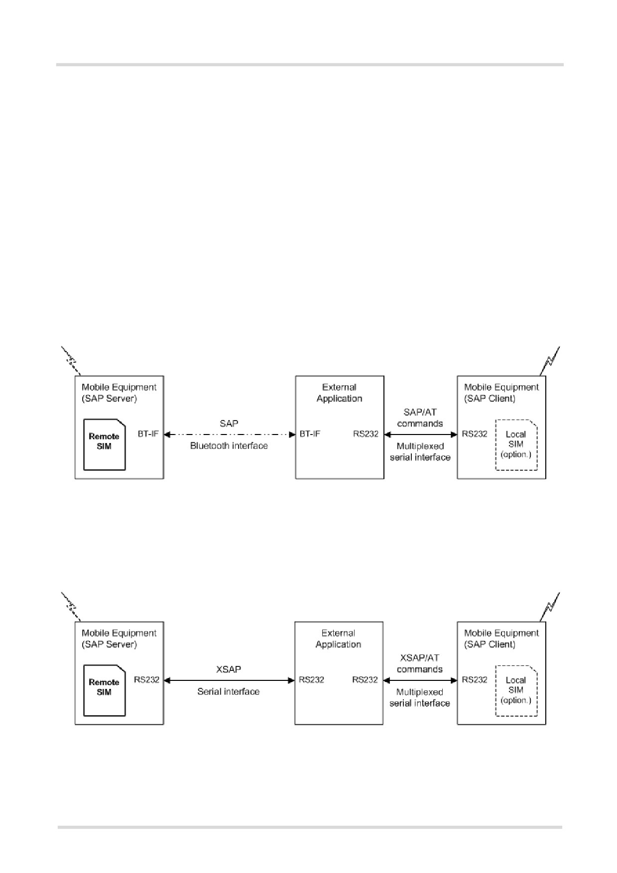
15.
Remote SIM Access (RSA) Commands
This chapter contains AT commands and responses related to the Remote SIM Access (RSA) feature of TC65i.
RSA allows TC65i to access and use a remote SIM card via its serial interface in addition to or instead of the SIM
locally attached via the dedicated lines on the interface connector.
The necessary protocols and procedures are implemented following the "SIM Access Profile (SAP) Interopera-
bility Specification" . As stated there it is possible for a SAP client to use a SIM card in an external device con-
nected via a wireless link. The external device can either be a mobile phone, a PDA or any other mobile
equipment that may be used as SIM card holder. The SIM Access Profile builds on the interface between the
mobile equipment and the SIM card (refer to the "Specification of the Subscriber Identity Module (GSM 11.11)"
[25]). For further details contact the Application Engineering Department at Cinterion Wireless Modules GmbH.
Figure 15.1, Basic Remote SIM Access Usage Scenario via Bluetooth illustrates an access scenario via Blue-
tooth:
Since the TC65i itself - acting as SAP client - does not control the Bluetooth wireless link, the communication
with the remote SIM needs to be routed via an external customer application. The external application estab-
lishes and controls the Bluetooth connection. It maps data received over a serial interface channel to data trans-
ferred over a Bluetooth interface and vice versa.
Figure 15.1: Basic Remote SIM Access Usage Scenario via Bluetooth
Figure 15.2, Basic Remote SIM Access usage scenario via RS232 illustrates an alternative access scenario via
a serial RS232 interface: Instead of Bluetooth it is possible for an external customer application to use a serial
RS232 interface in mapping data for the remote SIM in an external device. In this case an ASCII coded string
format (XSAP by Cinterion Wireless Modules GmbH) is used instead of the binary SAP data format employed
for Bluetooth.
Figure 15.2: Basic Remote SIM Access usage scenario via RS232

below.
SAP server
The SAP server has direct (galvanic) access to a SIM. It acts as a SIM card reader which assists the SAP client
in accessing and controlling this SIM via the serial link.
After RSA activation, the SAP server waits for SAP CONNECTION_REQ messages from the SAP client (see
Figure 15.3, SIM usage states of SAP server). The SAP server still uses its local SIM card until the parameter
negotiation with an SAP client has been accomplished successfully.
Figure 15.3: SIM usage states of SAP server
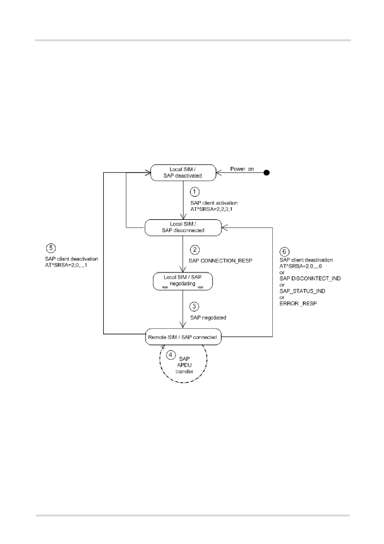
After RSA activation, the SAP client starts sending SAP CONNECTION_REQ messages (see Figure 15.4, SIM
usage states of SAP client). The SAP client still uses its local SIM until an SAP server responds and the param-
eter negotiation has been accomplished successfully. When the SAP client recognizes from the received ATR
data that the SIM of the SAP server is appropriate and uses the correct transmission protocols, it switches over
to the server's SIM. The "^SRSA: 2,2,1" URC notifies the SAP client that the server's SIM is accessible. Now, the
SAP client can enter the SIM PIN of the server's SIM. Both sides start to exchange APDU data.
When the SIM PIN authentication has been completed, the SAP client can register to the cellular network - via
the SIM inserted in the SAP server instead of its own local SIM.
As an additional option, the SAP client is advised to enable further URCs to get detailed status information during
connection setup, such as the URCs "^SCKS" and "+CREG". See the example provided in Section 15.2,
AT^SRSM.
Figure 15.4: SIM usage states of SAP client
15.1
AT^SRSA Remote SIM Access Activation
The AT^SRSA write command enables and disables RSA connections and allows to control the TC65i's SIM
usage scheme.
The AT^SRSA read command requests the current RSA status. Every line indicates an RSA connection, if any.
Syntax
Test Command
AT^SRSA=?
Response(s)
^SRSA:(list of supported <devId>s) , (list of supported <sapRole>s) , (list of supported <muxChan>s) , (list
of supported <dataForm>s) , (list of supported <beaconPer>s) , (list of supported <discType>s)
OK
Read Command
AT^SRSA?
Response(s)
[^SRSA:<devId>, <sapRole>, <connState>, <muxChan>, <dataForm>, <beaconPer>]
OK
Write Command
AT^SRSA=<devId>, <sapRole>[, <muxChan>[, <dataForm>[, <beaconPer>[, <discType>]]]]
Response(s)
^SRSA:<actResult>
OK
PIN ASC0 ASC1
USB MUX1 MUX2 MUX3 Charge
4
Last
-
+
+
+
+
+
+
-
-
-
Unsolicited Result Code
^SRSA: <devId>, <sapRole>, <connState>
This URC is generated if either the SIM usage scheme or the SAP connection status has changed due to SAP
message communication or AT command control.
Parameter Description
<actResult>(num)
Activation result
0
No Error
Parameters valid, SAP mode change initiated. However, actual mode change
is signaled via URC "^SRSA".
Other values indicate invalid activation requests, no SAP mode change is initi-
ated in the following cases:
1
Error unspecified.
2
Error activation command is busy.
3
Error activation started with serial multiplex mode is off.
4
Error activation started on invalid serial multiplex channel.
5
Error device Id is already known.
6
Error SAP mode is already active.
7
Error invalid parameter.
<devId>(num)
Device identification
Arbitrary number assigned on RSA activation by the host. Used for all subsequent RSA communication (AT
commands and URCs) during the activated session. Different numbers shall be used for SAP server and client.
1...100
<sapRole>(num)
SIM usage scheme of the TC65i
Direct switch from SAP server to SAP client mode and vice versa is not supported.
0(P)
Local SIM
If this parameter value is used with write command meaning depends on
parameter <discType>.
1
SAP server
Enables Remote SIM Access and configures the TC65i as SAP server.
The SAP server waits for CONNECT_REQ messages sent from the SAP client
until the right <MaxMsgSize> is negotiated. Once the SAP client sends a
CONNECT_REQ message with <MaxMsgSize> 276, the SAP server dereg-
isters from the network and then acts as SIM card reader.
However, under the following conditions the SAP server will not react to
CONNECT_REQ messages:
• during any calls (voice or data),
• if a GPRS context is activated,
• if Remote-SAT interface is activated (AT^SSTA) and a proactive command
is ongoing.
2
SAP client
Enables Remote SIM Access and configures the TC65i as SAP client.
The SAP client starts sending CONNECT_REQ messages periodically, until
the right
<MaxMsgSize> is negotiated. The intervals between sending
CONNECT_REQ messages are set with <beaconPer>. The SAP client
deregisters from the network if a local SIM was used before and switches to
the remote SIM after receiving all of the following messages from the SAP
server:
• the SAP message CONNECT_RESP,
• the SAP message STATUS_IND
• and, finally, the SAP message ATR_RESP received after the appropriate
request was issued by the client.
However, under the same conditions listed above for <sapRole>=1, the SAP
client will not send CONNECT_REQ messages, nor will it switch to the remote
SIM.
(num)
<muxChan>
Serial multiplexer channel number
Logical channels 2 and 3 can be reserved for RSA traffic on serial interface multiplexer. Multiplex mode shall be
enabled before RSA activation via AT+CMUX.
Note:
Number of multiplex channels is implementation specific, please refer to AT+CMUX and the multiplex documen-
tation supplied with the TC65i. If for instance three logical channels are implemented these are referenced as
numbers 1 - 3. The selected multiplexer channel is dedicated to the RSA communication. However, it is not pos-
sible to reserve logical channel number 1 for RSA traffic because only on this channel the TC65i can perform
circuit switched data transfer, e.g. FAX or data calls. If no channel is specified the ME uses the channel on which
the command was issued.
<dataForm>(num)
SAP message data format
[0]
XSAP ATC/URC format
SAP messages are translated into ASCII coded strings and transmitted as
parameters of the AT^SRSM command and the "^SRSM" URC. When using a
Bluetooth modem with AT command interface for transmitting data, it is recom-
mended to choose the XSAP data format. Note that AT commands not related
to RSA shall not be used after RSA activation on the dedicated serial multi-
plexer channel.
1
SAP transparent binary format
SAP messages are transmitted as coded in the SAP specification. This data
format should be selected for transmitting SIM data to a Bluetooth stack which
is part of the application. The binary data will be exchanged transparently with
the ME. However, the SAP data format does not need ASCII character conver-
sion. As a result less data will be transferred and the SIM communication will
be faster.
<beaconPer>(num)
Beacon period
0...[6]...100
Specifies the number of seconds the SAP client waits before sending the next
CONNECT_REQ message. A 0 value leads to a one-time connection request.
This parameter is applicable for SAP client activation only.
<discType>(num)
SAP disconnection type
This parameter is only applicable if <sapRole> equals 0.
Calls or active GPRS contexts via a remote SIM will be lost due to missing SIM access. Use of AT+CLCC is rec-
ommended to query call states before RSA deactivation.
0
Hold SAP role
SAP connection is going to be disabled. The TC65i remains in SAP mode and
is ready to (re)establish an SAP connection. If an SAP connection was ongoing
a URC "^SRSA: <devId>, <sapRole>, <connState>" with <connState>=
0 is issued.
• A server exclusively sends an SAP message DISCONNECT_IND (type
"Graceful") to the client.
• A client saves the SIM data temporarily held in the TC65i's memory to the
remote SIM and sends the DISCONNECT_REQ message to the server. If
requested the client restarts sending CONNECTION_REQ messages. If a
local SIM is attached the TC65i will use it to register to the network until a
server offers its SIM again.
[1]
Stop SAP operation
SAP connection is disabled and TC65i is forced to local SIM mode. A URC
"^SRSA: <devId>, <sapRole>, <connState>" with <sapRole>= 0 and
<connState>= 0 is issued.
• A server sends a DISCONNECT_IND message (type "Immediate") to the
client and returns to local SIM mode immediately. SIM data temporarily held
in the client's memory would be lost.
• A client exclusively sends the DISCONNECT_REQ message to the server.
Without saving temporarily held data to a remote SIM or waiting for
DISCONNECT_RESP the client immediately returns to local SIM mode.
<connState>(num)
SAP connection state
0
No SAP connection established.
1
SAP connection ongoing, i.e. peers exchange messages.
Notes
• If AT^SRSA with <dataForm> set to 1 (SAP) is given on the same serial multiplex channel as specified with
parameter <muxChan> the SAP data transfer mode is entered immediately. Therefore no command response
is issued by the TC65i in this case.
• If a TC65i acting as SAP client switches to a remote SIM card, it needs to load data from the SIM card first.
The duration of the initial data load varies depending on the SIM card. Users should be aware that during this
time SIM related AT commands (e.g. Phonebook or SMS commands) cannot be used. Therefore, it is recom-
mended to activate the "^SSIM READY" which indicates when the SIM card is accessible. See AT^SSET for
detail.
• If the TC65i is acting as SAP server and has released its SIM to a client it considers it as not accessible.
Therefore AT commands which require SIM access will be rejected with "+CME ERROR: SIM not inserted".
• Parameters <muxChan>, <dataForm> and <beaconPer> are applicable for RSA activation only.
15.2
AT^SRSM Remote SIM Access Message
The AT^SRSM command is used to transfer SAP messages between devices acting as SAP server and client. It
is applicable for XSAP data format only, for details please refer to the <dataForm> parameter of the AT^SRSA
command. The write command transports SAP messages to an SAP server or SAP client.
Syntax
Test Command
AT^SRSM=?
Response(s)
OK
Write Command
AT^SRSM=<RsaDevId>, <RsaMsgId>[, <RsaMsgData>[, <RsaMsgLen>[, <RsaMsgRc>]]]
Response(s)
OK
PIN ASC0 ASC1
USB MUX1 MUX2 MUX3 Charge
4
Last
-
+
-
+
+
+
+
-
-
-
Unsolicited Result Code
^SRSM: <RsaDevId>, <RsaMsgId>[, <RsaMsgData>[, <RsaMsgLen>[, <RsaMsgRc>]]]
This URC is issued by an ME acting as SAP server or client to transfer SAP message data.
Parameter Description
<RsaDevId>(num)
RSA device identification
Number assigned by the host on RSA activation via AT^SRSA, parameter <devId>.
<RsaMsgId>(num)
RSA message identification
For details refer to Section 15.2.1, SAP Request Message Parameters and Section 15.2.2, SAP Response Mes-
sage Parameters.
<RsaMsgData>(str)
RSA message data
For details refer to Section 15.2.1, SAP Request Message Parameters and Section 15.2.2, SAP Response Mes-
sage Parameters.
<RsaMsgLen>(num)
RSA message data length
For details refer to Section 15.2.1, SAP Request Message Parameters and Section 15.2.2, SAP Response Mes-
sage Parameters.
<RsaMsgRc>(num)
RSA message result code
For details refer to Section 15.2.1, SAP Request Message Parameters and Section 15.2.2, SAP Response Mes-
sage Parameters.
<MaxMsgSize>(num)
SAP parameter MaxMsgSize
Handling of this parameter is as follows:
• If the TC65i is acting as SAP client the requested value of <MaxMsgSize> is 300. During SAP connection
setup this value may be negotiated with the server to the minimal value 274, which is calculated by 256 data
bytes as part of a TRANSFER_APDU_RESP message plus a 16 byte SAP header and two status bytes. If
the server does not accept this value range no SAP connection will be established.
• If the TC65i is acting as SAP server it requires that a <MaxMsgSize> value of 276 will be accepted by a
connected client.
<ConnStatus>(num)
SAP parameter Connection Status
<DiscType>(num)
SAP parameter Disconnection Type
<CmdApdu>(str)
SAP parameter Command APDU or Command APDU7816
<CmdApduLen>(num)
SAP parameter Command APDU length
<RspApdu>(str)
SAP parameter Response APDU
<RspApduLen>(num)
SAP parameter Response APDU length
<ATR>(str)
SAP parameter ATR
<AtrLen>(num)
SAP parameter ATR length
<ResCode>(num)
SAP parameter Result Code
<CardRdStatus>(num)
SAP parameter Card Reader Status
<StatusChange>(num)
SAP parameter Status Change
<TransportProtocol>(num)
SAP parameter Transport Protocol
Example
The following example shows how to establish an RSA connection.
AT+CMEE=2
Switch on verbose error messages.
OK
AT+CREG=1
OK
Switch on network registration URC.
AT^SSET=1
Switch on SIM data ready URC.
OK
AT^SCKS=1
Switch on SIM status URC.
OK
AT^SM20=0
Switch on immediate indication of OK response after
dialing with ATD.
OK
AT^SRSA?
Does the ME support RSA and is a SAP connection
established?
OK
AT^SRSA=2,2,3,0
Initialization of RSA mode using XSAP data format.
^SRSA:0
OK
^SRSA:2,2,0
URC indicating SAP client start without ongoing con-
nection.
ME now starts sending SAP message
CONNECTION_REQ on dedicated RSA channel.
If an SAP server has responded and offers its SIM:
^SRSA:2,2,1
URC indicating a connection with SAP server.
^SCKS:0
URC indicating the loss of (local) SIM.
+CREG:0
URC indicating the deregistration from network
because of loss of SIM.
^SCKS:1
URC indicating the activation of remote SIM.
ME now starts reading data from the SIM.
Does the new SIM require a PIN?
AT+CPIN?
Request PIN status.
+CPIN: SIM PIN
PIN needs to be entered.
OK
or
+CME ERROR: SIM blocked
or
+CME ERROR: SIM busy
Retry if the ME returns these messages.
AT+CPIN=1234
OK
+CREG:2
+CREG:1
URC indicating network registration.
^SSIM READY
URC indicating that SIM data is read out.
ATD491777777777777
OK
Make a call.
15.2.1
SAP Request Message Parameters
The table below shows all SAP request message parameters sent
• when an "^SRSM" URC is issued by an ME acting as SAP client
• and then the AT^SRSM write command is used to transfer data to the SAP server.
SAP Request Message Parameter Mapping:
Id
SAP Message Name
SAP parameter mapping to AT^SRSA parame-
ters
<RsaMsgId> [,<RsaMsgData> [,<RsaMs-
gLen> [,<RsaMsgRc>]]]
0
CONNECT_REQ
0,,<MaxMsgSize>
2
DISCONNECT_REQ
2
5
TRANSFER_APDU_REQ
5,<CmdApdu>,<CmdApduLen>
7
TRANSFER_ATR_REQ
7
9
POWER_SIM_OFF_REQ
9
11
POWER_SIM_ON_REQ
11
13
RESET_SIM_REQ
13
15
TRANSFER_CARD_READER _STATUS_REQ
15
19
SET_TRANSPORT_PROTOCOL_REQ
19,<TransportProtocol>
15.2.2
SAP Response Message Parameters
The table below shows all SAP response and indication message parameters sent when
• an "^SRSM" URC is issued by an ME acting as SAP server
• and then the AT^SRSM write command is used to transfer data to the SAP client.
SAP Response Message Parameter Mapping:
Id
SAP Message Name
SAP parameter mapping to AT^SRSA parame-
ters
<RsaMsgId> [,<RsaMsgData> [,<RsaMs-
gLen> [,<RsaMsgRc>]]]
1
CONNECT_RESP
1,,<MaxMsgSize>,<ConnStatus>
3
DISCONNECT_RESP
3
4
DISCONNECT_IND
4,,,<DiscType>
6
TRANSFER_APDU_RESP
6,<RspApdu>,<RspApduLen>,<ResCode>
8
TRANSFER_ATR_RESP
8,<ATR>,<AtrLen>,<ResCode>
10
POWER_SIM_OFF_RESP
10,,,<ResCode>
12
POWER_SIM_ON_RESP
12,,,<ResCode>
14
RESET_SIM_RESP
14,,,<ResCode>
16
TRANSFER_CARD_READER
16,,<CardRdStatus>,<ResCode>
_STATUS_RESP
17
STATUS_IND
17,,,<StatusChange>
18
ERROR_RESP
18
20
SET_TRANSPORT_PROTOCOL_RESP
20,,,<ResCode>
15.3
Related AT Commands
The following commands might be of interest while using the RSA feature.
• AT^SCKS
This AT command is used to check the current status of the SIM (local or remote).
• AT^SSET
After power on and personalization (PIN entry if required), the ME starts reading data from the SIM. Please
keep in mind that after entering the PIN, even after the TE sends "OK", subsequent commands that need
access to data stored on the SIM may be blocked for up to 30 seconds. It may take even longer to access the
remote SIM depending on the establishment of the RSA communication link. Therefore, it is recommended
to take advantage of the "^SSIM READY" URC enabled with the AT^SSET command. This URC notifies the
user when the process of reading SIM has completed. Afterwards all commands regarding to SIM data files
can be used, e.g. the SMS and phonebook commands.
• AT^SLCC
This command is recommended for querying the state of current calls. A list of all active calls will be returned.
This is especially important when the user wants to terminate the SAP connection using
AT^SRSA=<devId>,<sapRole>,,,,<discType>; with <sapRole> set to 0 and <discType> set to 1. All
calls or active GPRS contexts established via remote SIM will be terminated and the ME will use the locally
attached SIM card.
• AT^SIND="simlocal",1
"+CIEV" "simlocal" URCs indicate the availability of a locally (i.e. physically) connected SIM.
• AT^SIND="simstatus",1
"+CIEV" "simstatus" URCs indicate the current status of a locally (i.e. physically) or remotely connected SIM.
• SIM data storage
It is recommended that all user relevant data are stored on the SIM only. For example, added phonebook and
SMS entries in the client's storage are not accessible after a RSA connection.
15.3.1
Establishing an RSA Connection in a PC Environment
To set up an RSA connection in a PC environment an appropriate PC application is needed. For test and eval-
uation purposes and as exemplary implementation guidance Cinterion Wireless Modules offers a PC application
called "ComBridge". For ordering details contact your local dealer. "ComBridge" provides basic features to sim-
ulate an RSA application environment, e.g. mapping of the SAP communication between a SAP server and cli-
ent. To support the different RSA coding modes (SAP and XSAP) and to transfer data between the two COM
ports, the PC application uses two variable modules (filters):
• XSAP filter
Translating the "^SRSM" URCs into the AT^SRSM command
• SAP filter
Transparently transfer binary SAP messages. The generic "1:1" filter ("software null modem") can also be
used for this purpose, but communication might be slower since it performs bytewise data transfer.
15.3.2
Bluetooth scenario (SAP)
A connection between a TC65i operating as an SAP client and a device that supports Bluetooth and SIM Access
profile requires:
a) System requirements
• Windows 2000, Windows XP (or later) installed
• USB Bluetooth dongle. The driver of the dongle must allow connections to Bluetooth profiles which are not
yet specified by the SIG, e.g. SAP.
b) Installation procedure
• After installing the USB Bluetooth dongle and the "PlugFree" driver software, the Bluetooth profiles are acces-
sible via their own virtual COM port.
• If the WinMux driver has been installed another three virtual channels (mapped to additional COM ports) are
available. The physical Multiplexer COM port is connected to the TC65i.
• Start the Bluetooth connection using the driver provided by the USB Bluetooth dongle.
• Through "ComBridge", one virtual COM port supplied by "WinMux" is connected to the SAP COM port of
"PlugFree". This establishes a direct communication link between the TC65i and the other mobile. However,
take into account that AT commands can still be entered on the remaining multiplexer channels of the TC65i.
• Select the "ComBridge" SAP filter.
• Press the "ComBridge-Start" button to connect both mobiles.
• Start the SAP client using the AT command "AT^SRSA=2,2,3,1", if multiplexer channel 3 is used.
15.3.3
Serial Interface Scenario (XSAP)
This example describes the connection of two mobiles. It is recommended that the instructions be followed in the
order that they are presented:
• Install two WinMux drivers on the PC and connect each ME to the physical port of a Multiplexer.
• Connect the PC application "ComBridge" to one virtual COM port of each Multiplexer. This establishes a com-
munication link between the two mobiles. Bear in mind that AT commands can still be issued on both mobiles
using the remaining serial channels.
• Select the "ComBridge" XSAP filter.
• Open the XSAP "Config Filter" menu and deactivate the "Startup - Send Initialization" and the "Shutdown -
Switch back to local SIM" tags. However, the appropriate device IDs need to be entered in the "Startup"
frame.
• Press the "ComBridge - start" button to connect both MEs.
• Start the SAP client via AT command "AT^SRSA=2,2,3,0", if multiplexer channel 3 is used.
• Start the SAP server via AT command "AT^SRSA=1,1,3,0", if multiplexer channel 3 is used.
15.3.4
RSA Connection via Java application
Remote SIM access is not supported by the module’s Java implementation. Please do not use RSA AT com-
mands in your Java applications.
16.
SIM Application Toolkit (SAT) Commands
This chapter offers a brief reference to AT commands and responses related to the TC65i's SIM Application Tool-
kit (SAT) implementation. A consistent and detailed description can be found in the "Remote-SAT User's Guide"
[4]. For further advice please contact the Application Engineering Department at Cinterion Wireless Modules
GmbH.
ETSI specification GSM 11.14 [26] defines SAT in detail.
SIM Application Toolkit (SAT) is a technology that allows an application running on the SIM to control the Mobile
Equipment (ME). Remote-SAT (RSAT) provides a link between applications located on the SIM and a customer
application (TA). The purpose of RSAT is to allow the TA to send AT commands to the SAT interface and to dis-
play all SAT activities on the user interface of the customer application.
Two groups of commands are exchanged between the SAT located on the TC65i and the SIM Application run-
ning on the SIM:
• Proactive commands are sent from the SIM application to the TC65i's SAT, such as "DISPLAY TEXT".
• Envelope commands are sent from the TC65i's SAT to the SIM application, such as "MENU SELECTION".
16.1
AT^SSTA SAT Interface Activation
The AT^SSTA write command can be used to specify the Remote-SAT activation mode <mode> and, if Explicit
Response mode is enabled, to explicitly activate the Remote SAT interface. Removing and inserting the SIM
does not affect the activation status.
SAT commands which are not using the AT interface (non MMI related SAT commands, e.g. PROVIDE LOCAL
INFORMATION) are executed without activating Remote-SAT.
The read command canbe used to request the current operating status and the used alphabet of the Remote-
SAT interface.
Syntax
Test Command
AT^SSTA=?
Response(s)
^SSTA:(list of supported <state>s), (list of supported <Alphabet>s)
OK
Read Command
AT^SSTA?
Response(s)
^SSTA: <state>, <Alphabet>, <allowedInstance>, <SatProfile>
OK
Write Command
AT^SSTA=<mode>[, <Alphabet>]
Response(s)
OK
PIN ASC0 ASC1
USB MUX1 MUX2 MUX3 Charge
4
Last
Reference(s)
-
+
+
+
+
+
+
-
+
-
CINTERION
Parameter Description
<state>(num)
TC65i Remote-SAT interface states
0
RESET
1
OFF
2
IDLE
3
PAC
4
WAIT
<Alphabet>(num)
Parameter is stored non-volatile and takes effect after next restart of the ME.
0(D)
GSM character set
Input of a character requests one byte, e.g. "Y".
1
UCS2
To display the 16 bit value of characters represented in UCS2 alphabet a 4 byte
string is required, e.g. "0059" is coding the character "Y". For details please
refer to ISO/IEC 10646.
<allowedInstance>(num)
0
SAT is already used on another instance (logical channel in case of the multi-
plex protocol). Only test and read commands can be used.
1
SAT may be started on this instance via the write version of this command.
<SatProfile>(str)
SAT profile according to GSM 11.14 [26]
The profile tells the SIM Application which features (e.g. proactive commands) are supported by the SIM Appli-
cation Toolkit implementation of the TC65i.
<mode>(num)
Select Remote SAT activation mode.
Parameter is stored non-volatile and takes effect after next restart of the ME. Removing and inserting the SIM
does not affect the activation status.
0(D)
Automatic response (AR) mode.
All commands and responses are exchanged automatically between the ME
and the SIM application. This eliminates the need to enter any Remote SAT AT
commands incl. the AT^SSTA command.
If AR mode is enabled the ME enters the OFF state (<state>=1) after reboot.
1
Explicit response (ER) mode.
This mode is intended for use with an MMI. If ER mode is enabled the MMI is
required to handle, via the module's Remote-SAT interface, all commands and
responses transmitted to or from the SIM.
If ER mode is enabled the ME enters the IDLE state (<state>= 2) after reboot.
16.2
^SSTN SAT Notification
Unsolicited Result Codes
URC 1
Proactive Command notification
^SSTN: <cmdType>
Every time the SIM Application issues a Proactive Command, via the ME, the TA will receive a notification.
This indicates the type of Proactive Command issued.
AT^SSTGI must then be used by the TA to request the parameters of the Proactive Command from the ME.
Upon receiving the ^SSTGI response from the ME, the TA must send AT^SSTR to confirm the execution of
the Proactive Command and provide any required user response, e.g. a selected menu item.
URC 2
Terminate Proactive Command notification
^SSTN: <cmdTerminateValue>
When the SIM application has issued a Proactive Command to the ME, it is possible that this command will
be terminated later. URC "^SSTN" is sent with a different Proactive Command type number (added terminate
offset 100) to indicate the termination of the specified command.
The state changes to idle. Therefore the TA should avoid sending any further commands related to the ter-
minated Proactive Command, e.g. AT^SSTGI or AT^SSTR.
URC 3
Notification that SIM Application has returned to main menu
^SSTN: 254
Notification to the TA when the SIM Application has finished a command cycle and again enters its main
menue, which was transferred with an URC "^SSTN: 37" (SET UP MENU) at start up.
This URC should be used to open this menue on the sreen.
The TA does not need to respond directly, i.e. AT^SSTR is not required.
URC 4
SIM reset notification
^SSTN: 255
Notification to the TA if a Proactive Command "REFRESH - SIM Reset" has been issued by the SIM Applica-
tion, please refer to AT^SSTGI.
This URC should be used to set the TAs application to its initial state since the SIM Application will start from
the beginning, too.
The TA does not need to respond directly, i.e. related AT^SSTGI and AT^SSTR are neither required nor
allowed.
Since the ME is still busy on SIM access the ME may respond with "+CME ERROR: SIM blocked" or "+CME
ERROR: SIM busy" on following PIN required AT Commands for a while. Then TA shall retry until the ME
responds with "OK". The time needed for this process depends on the SIM and may take more than 10 sec-
onds.
Parameter Description
<cmdType>(num)
Proactive Command number
<cmdTerminateValue>(num)
Defined as <cmdType> + terminate offset. The terminate offset equals 100.
16.3
AT^SSTGI SAT Get Information
Regularly this command is used upon receipt of an URC "^SSTN" to request the parameters of the Proactive
Command.
Then the TA is expected to acknowledge the AT^SSTGI response with AT^SSTR to confirm that the Proactive
Command has been executed. AT^SSTR will also provide any user information, e.g. a selected menu item.
The Proactive Command type value specifies to which "^SSTN" the command is related.
Syntax
Test Command
AT^SSTGI=?
Response(s)
^SSTGI:(list of supported <state>s), (list of supported <cmdType>s)
OK
Read Command
AT^SSTGI?
Response(s)
^SSTGI: <state>, <cmdType>
OK
Write Command
AT^SSTGI=<cmdType>
Response(s)
OK
ERROR
+CME ERROR: <err>
PIN ASC0 ASC1
USB MUX1 MUX2 MUX3
Charge
4
Last
Reference(s)
-
+
+
+
+
+
+
-
+
-
CINTERION
Parameter Description
<state>(num)
TC65i Remote-SAT interface states
0
RESET
1
OFF
2
IDLE
3
PAC
4
WAIT
<cmdType>(num)
Related Proactive Command
16.4
AT^SSTR SAT Response
The TA is expected to acknowledge the AT^SSTGI response with AT^SSTR to confirm that the Proactive Com-
mand has been executed. AT^SSTR will also provide any user information, e.g. a selected menu item.
Syntax
Test Command
AT^SSTR=?
Response(s)
^SSTR:(list of supported <state>s), (list of supported <cmdType>s)
OK
Read Command
AT^SSTR?
Response(s)
^SSTR: <state>, <cmdType>
OK
Write Command
AT^SSTR=<cmdType>, <status>[, <inputNumber>][, <inputString>][, <statAddInfo>]
Response(s)
OK
PIN ASC0 ASC1
USB MUX1 MUX2 MUX3 Charge
4
Last
Reference(s)
-
+
+
+
+
+
+
-
+
-
CINTERION
Parameter Description
<state>(num)
TC65i Remote-SAT interface states
0
RESET
1
OFF
2
IDLE
3
PAC
4
WAIT
<cmdType>(num)
Number related to Proactive Command or event type according to GSM 11.14 [26].
<status>(num)
Command status return regarding the type of action that has taken place, e.g. action performed by the user.
Values are in accordance with GSM 11.14 [26].
<inputNumber>(num)
Response number entered by user
<inputString>(str)
Response string entered by user
<statAddInfo>(num)
Optional additional command status; for possible values refer to GSM 11.14 [26].
17.
Phonebook Commands
The AT commands described in this chapter allow the external application to access the phonebooks located in
the TC65i's memory or on the attached Subscriber Identity Module (SIM).
17.1
Sort Order for Phonebooks
Due to the support of UCS2 for the <text> part of phonebook entries, the sort order for phonebook records fol-
lows the algorithm published as Unicode Technical Standard #10, "Unicode Collation Algorithm".
A memory-optimized version of the proposed collation tables "[AllKeys]" from Unicode Technical Standard #10
is used in order to determine collation weights for Code points between 0000 and 06FF, and composed keys are
used for Code points from ranges 0700 to 33FF, A000 to D7FF and E000 to FFFD. Code Points not referenced
in these tables will be assigned a default collation weight with their unicode value as level 1 weight. Decomposi-
tion is not supported.
Phonebook entries whose names contain only characters from the GSM07.07 default alphabet are converted
internally into their UCS2 equivalents in order to achieve consistent sorting results.
For the user, this means that:
• Punctuation marks and other non-alphabetical characters from the common latin-based character sets, and
from the standard GSM character set, will be sorted before any alphabetical characters. The ordering in which
these marks appear as compared to other non-alphabetical characters from the same group is determined
by their collation weights and does not reflect their code values in the UCS2 or GSM alphabet tables above.
Please refer to www.unicode.org for detail.
• Alphabetical characters from the common latin-based character sets, and from the standard GSM character
set, will be sorted according to their underlying base characters, plus the collation weights of their accent
signs.
• Only collation levels 1 and 2 are regarded, so sorting is not case-sensitive.
Example: the european letters "Å" (GSM 0EH, UCS2 00C5h), "æ" (GSM 1DH, UCS2 00E6h), "ç" (GSM09h,
UCS2 00E7h), "a" (GSM 61H, UCS2 0061h ) and "b" (GSM 62H, UCS2 0062h) will be sorted in order "a", "Å",
"æ" "b","ç" although their numerical values in GSM and UCS2 suggest a different ordering.
17.2
AT+CNUM Read own numbers
AT+CNUM returns the subscribers own number(s) from the SIM.
Syntax
Test Command
AT+CNUM=?
Response(s)
OK
Exec Command
AT+CNUM
Response(s)
[+CNUM: [<alpha>], <number>, <type>]
[+CNUM: ... ]
OK
ERROR
+CME ERROR: <err>
PIN ASC0 ASC1
USB MUX1 MUX2 MUX3 Charge
4
Last
Reference(s)
+
+
+
+
+
+
+
-
+
-
GSM 07.07
Parameter Description
<alpha>(str)
Optional alphanumeric string associated with <number>.
<number>(str)
Phone number in format specified by <type>.
<type>(str)
Type of address octet, see also: AT+CPBR <type>.
Note
• Users should be aware that when using this AT command quickly after SIM PIN authentication the SIM data
may not yet be accessible, resulting in a short delay before the requested AT command response is returned.
See Section 23.1, Restricted access to SIM data after SIM PIN authentication for further detail.
17.3
AT+CPBR Read from Phonebook
AT+CPBR serves to read one or more entries from the phonebook selected with AT command AT+CPBS.
The AT+CPBR test command returns the location range supported by the current phonebook storage, the maxi-
mum length of <number> field and the maximum length of <text> field.
Note: Length information may not be available while SIM storage is selected. If storage does not offer format
information, the format list contains empty parenthesizes.
The AT+CPBR write command determines the phonebook entry to be displayed with <location1> or a location
range from
<location1> to <location2>. Hence, if no <location2> is given
only
the
entry
at
<location1> will be displayed.
If no entries are found at the selected location "OK" will be returned.
Syntax
Test Command
AT+CPBR=?
Response(s)
+CPBR: (1-<maxloc>), <nlength>, <tlength>
OK
ERROR
+CME ERROR: <err>
Write Command
AT+CPBR=<location1>[, <location2>]
Response(s)
[+CPBR: <location1>, <number>, <type>, <text>]
[+CPBR: <location2>, <number>, <type>, <text>]
OK
ERROR
+CME ERROR: <err>
PIN ASC0 ASC1
USB MUX1 MUX2 MUX3 Charge
4
Last
Reference(s)
+
+
+
+
+
+
+
-
+
-
GSM 07.07, GSM
11.11
Parameter Description
<location1>(num)
The first (lowest) location number within phonebook memory where to start reading. The maximum range sup-
ported by the current phonebook is given in the test command response.
If
<location1> exceeds the upper bound <maxloc> (as indicated by the test command), command will
respond with "+CME ERROR: invalid index".
<location2>(num)
The last (highest) location number within phonebook memory where to stop reading. The maximum range sup-
ported by the current phonebook is given in the test command response.
If both <location1> and <location2> are in the range indicated by the test command parameter <max-
loc>, the list of entries will be output and terminated with "OK".
If <location2> exceeds the range indicated by the test command parameter <maxloc>, the list of entries will
be output but terminated with "+CME ERROR: invalid index".
Note: The maximum value of <location2> is 255, regardless of the phonebook type and its range indicated
by <maxloc>. If a value greater than 255 is used the query returns no phonebook records, and only "+CME
ERROR: invalid index" is shown.
<number>(str)
Phone number in format specified by <type>, it may be an empty string.
<type>(num)
Type of address octet, which defines the used type of number (ton) and the numbering plan identification (npi).
Please consider that for types other than 129 or 145 dialing from phonebook with ATD><mem><n> is, depending
on the network, not always possible (refer to GSM 04.08 subclause 10.5.4.7 for details). See also <type> of
AT+CPBW.
Possible values are:
145
Dialing string <number> includes international access code character '+'
161
National number. Network support of this type is optional.
209
Dialing string <number> has been saved as ASCII string and includes non-
digit characters other than "*", "#" or "+". Note that phonebook entries saved
with this type cannot be dialed.
255
Dialing string <number> is a command to control a Supplementary Service,
i.e. "*", "#" codes are contained. Network support of this type is optional.
129
Otherwise
<text>(str)(+CSCS)
Text assigned to a phone number. The maximum length for this parameter is given with test command response
parameter <tlength>.
If using an ASCII terminal characters which are coded differently in ASCII and GSM have to be entered via
escape sequences as described in Section 1.6, Supported character sets.
<maxloc>(num)
Maximum location number for the currently selected storage. For phonebooks located on the SIM this value
depends on the SIM card type.
<nlength>(num)
Maximum length of phone number for "normal" locations. Depending on the storage a limited number of loca-
tions with extended memory is available per phonebook. These locations allow storing numbers with twice the
standard length, which is 2*<nlength> digits for normal numbers, but only <nlength> digits for numbers
saved with <type>=209.
<tlength>(num)
Maximum length of <text> assigned to the telephone number. The value indicated by the test command is
given in octets. If <text> is given as GSM characters each character corresponds to one octet. If the <text>
string is given in UCS2, the maximum number of characters depends on the coding scheme used for the alpha
field of the SIM according to GSM 11.11, Annex B [25]. In the worst case the number of UCS2 characters is at
least one less than half the number of GSM characters.
Note
• Users should be aware that when using this AT command quickly after SIM PIN authentication the SIM data
may not yet be accessible, resulting in a short delay before the requested AT command response is returned.
See Section 23.1, Restricted access to SIM data after SIM PIN authentication for further detail.
Example
AT+CPBR=?
First run the AT+CPBR test command to find out the
maximum range of entries stored in the active
phonebook.
+CPBR:(1-100),20,17
TC65i returns the supported values, where 100 is the
supported range of location numbers,
20 is the
length of the phone number and 17 is the maximum
length of the associated text.
AT+CPBR =1,3
Then use the AT+CPBR write command to display
+CPBR:1,"+999999",145,"Charlie"
the phonebook entries sorted by location numbers.
+CPBR:2,"+777777",145,"Bill"
+CPBR:3,"+888888",145,"Arthur"
17.4
AT+CPBS Select phonebook memory storage
AT+CPBS selects the active phonebook storage, i.e. the phonebook storage that all subsequent phonebook com-
mands will be operating on.
The read command returns the currently selected <storage>, the number of <used> entries and the <total>
number of entries available for this storage. The test command returns all supported <storage>s as compound
value.
Syntax
Test Command
AT+CPBS=?
Response(s)
+CPBS: (list of supported <storage>s)
OK
ERROR
+CME ERROR: <err>
Read Command
AT+CPBS?
Response(s)
+CPBS: <storage>, <used>, <total>
OK
ERROR
+CME ERROR: <err>
Write Command
AT+CPBS=<storage>
Response(s)
OK
ERROR
+CME ERROR: <err>
PIN ASC0 ASC1
USB MUX1
MUX2 MUX3
Charge
4
Last
Reference(s)
+
+
+
+
+
+
+
-
+
-
GSM07.07
Parameter Description
<storage>(str)
“FD“
Fixed dialing phonebook
Capacity: depending on SIM
Location: SIM
“SM“(&F)(P)
SIM phonebook
Capacity: depending on SIM
Location: SIM
“ON“
MSISDN list
Capacity: depending on SIM
Location: SIM
“ME“
Mobile Equipment Phonebook
Capacity: max. 250 entries
Location: ME
“LD“
Last number dialed phonebook. Stores all voice call numbers dialed with ATD,
but no data call numbers.
Capacity: max. 10 entries
Location: ME
AT+CPBW command is not applicable to this storage. The LD list can be deleted
with AT^SDLD or with AT^SPBD.
“MC“
Missed (unanswered received) calls list
Capacity: max. 10 entries
Location: ME
AT+CPBW command is not applicable to this storage. The MC list can be
deleted with AT^SPBD.
“RC“
Received calls list
Capacity: max. 10 entries
Location: ME
AT+CPBW command is not applicable to this storage. The RC list can be
deleted with AT^SPBD.
“VM“
CPHS voice mailbox phonebook
Capacity: 1 or 2 entries, depending on SIM
1 - Line 1 mailbox
2 - Line 2 mailbox
Location: SIM
<used>(num)
Value indicating the number of used locations in selected memory storage.
<total>(num)
Value indicating the maximum number of locations allowed in the selected memory storage.
Notes
• Users should be aware that when using this AT command quickly after SIM PIN authentication the SIM data
may not yet be accessible, resulting in a short delay before the requested AT command response is returned.
See Section 23.1, Restricted access to SIM data after SIM PIN authentication for further detail.
• If the SIM card is changed, all records of the "MC", "RC" and "LD" phonebooks stored on the ME will be
deleted automatically. If the same SIM is removed and reinserted, no automatic deletion is performed. Calls
made after last switch-on will be cleared from the "MC", "RC" and "LD" phonebook, if the SIM is removed and
reinserted during normal operation.
• The following call history rule applies to the phonebook types "LD", "MC" and "RC":
When the same number is dialed several times in direct succession the "LD" phonebook will store one single
entry. When dialed several times, but in a row with different numbers, the same number will be logged each
time after dialing, resulting in double or multiple "LD" phonebook entries related to this number.
The optional <text> in AT+CPBW write command must be stored in any phonebook when reading the
<text> with AT+CPBR write command in the "LD" phonebook after having dialed with ATD or another dial
command.
Likewise, the "MC" or "RC" phonebook will store only a single entry when calls from the same number are
received in direct succession, and double or multiple entries when calls from the same number are received
several times, but amongst other incoming calls from different numbers.
17.5
AT+CPBW Write into Phonebook
The AT+CPBW write command can be used to create, edit and delete a phonebook entry at a <location> of
the active storage selected with AT+CPBS.
If <storage>="FD" (SIM fixed dialing numbers) is selected, PIN2 authentication has to be performed prior to
any write access.
The AT+CPBW test command returns the location range supported by the current storage, the maximum length
of the <number> field, the range of supported <type> values and the maximum length of the <text> field.
Note: The length may not be available while SIM storage is selected. If storage does not offer format information,
the format list contains empty parenthesizes.
Syntax
Test Command
AT+CPBW=?
Response(s)
+CPBW: (1-<maxloc>), <nlength>, (list of supported <type>s), <tlength>
OK
ERROR
+CME ERROR: <err>
Write Command
AT+CPBW=[<location>][, <number>[[, <type>][, <text>]]]
Response(s)
OK
ERROR
+CME ERROR: <err>
PIN ASC0 ASC1
USB MUX1 MUX2 MUX3 Charge
4
Last
Reference(s)
+
+
+
+
+
+
+
-
+
-
GSM 07.07, GSM 04.08
Parameter Description
<location>(num)
Location number within phonebook memory. The maximum range supported by each storage type is indicated
in the test command response. If <location> is not given, the first free entry will be used.
If <location> is given as the only parameter, the phonebook entry specified by <location> is deleted.
<number>(str)
Phone number in format specified by <type>. Parameter must be present, although it may be an empty string.
Alphabetic characters are not permitted. <number> may contain dialstring modifiers "*", "#" or "+".
If other printable non-alphabetic characters are used the entry needs to be saved with <type>=209. Otherwise,
if <type>=209 is not used any non-digit characters other than "*", "#" or "+" will be removed from the string and
only accepted modifiers from the GSM alphabet will be saved.
A <number> saved with <type>=209 requires double memory. In order to fit into a standard location, the num-
ber needs to be reduced to a maximum length of <nlength>/2, including all digits and dial string modifiers.
Extended locations may be used as stated below for <nlength>.
<type>(num)
Type of address octet, which defines the used type of number (ton) and the numbering plan identification (npi).
Please consider that for types other than 129 or 145 dialing from phonebook with ATD><mem><n> is, depending
on the network, not always possible (refer GSM 04.08 subclause 10.5.4.7 for details).
If <type> is not specified the unknown <type>=129 is used. If <number> contains a leading "+" <type>=145
(international) is used.
Supported values are:
145
Dialing string <number> includes international access code character "+"
161
National number. The network support for this type is optional.
209
Dialing string <number> will be saved as ASCII string.
This is the default value, if <type> is not specified explicitly and characters
other than "*", "#" or "+" are included in <number>.
Note that phonebook entries saved with this type cannot be dialed.
255
Dialing string <number> is a command to control a Supplementary Service,
i.e. "*", "#" codes are contained. Network support of this type is optional.
129
Unknown number. If <type> is unknown and the <number> contains a lead-
ing "+", <type>=145 (international) is used.
<text>(str)(+CSCS)
Text assigned to the phone number. The maximum length of this parameter is given in the test command
response <tlength>. When using an ASCII terminal, characters which are coded differently in ASCII and GSM
have to be entered via escape sequences as described in Section 1.6, Supported character sets.
<maxloc>(num)
Maximum number of locations supported by the currently selected storage. For phonebooks located on SIM,
this value varies depending on the SIM card. See AT+CPBS for typical values.
<nlength>(num)
Maximum length of phone number for "normal" locations. Depending on the storage, a limited number of loca-
tions with extended memory is available per phonebook. These locations allow storing numbers with twice the
standard length, which is 2*<nlength> digits for normal numbers, but only <nlength> digits for numbers
saved with parameter <type>= 209. If all extended locations of the selected phonebook are used up, then any
attempt to write a number which requires extended memory will be denied with "+CME ERROR: invalid dial
string".
<tlength>(num)
Maximum length of <text> assigned to the telephone number. The value indicated by the test command is
given in octets. If the <text> string is given in GSM characters, each character corresponds to one octet. If the
<text> string is given in UCS2, the maximum number of characters depends on the coding scheme used for
the alpha field of the SIM. In the worst case the number of UCS2 characters is at least one less than half the
number of GSM characters.
For a detailed description please refer to GSM 11.11, Annex B [25].
Notes
• Users should be aware that when using this AT command quickly after SIM PIN authentication the SIM data
may not yet be accessible, resulting in a short delay before the requested AT command response is returned.
See Section 23.1, Restricted access to SIM data after SIM PIN authentication for further detail.
• During AT+CPBW write command it is possible that in some cases returns "+CME ERROR: operation tempo-
rary not allowed". Use AT+CPBW write command again.