Physics For Scientists And Engineers 6E - part 298
S E C T I O N 37. 6 • Interference in Thin Films
1189
the two-slit interference pattern. Instead, we observe a dark fringe at point P+. From
this, we conclude that a 180° phase change must be produced by reflection from the
mirror. In general,
an electromagnetic wave undergoes a phase change of 180°
upon reflection from a medium that has a higher index of refraction than the
one in which the wave is traveling.
It is useful to draw an analogy between reflected light waves and the reflections of
a transverse wave pulse on a stretched string (Section 16.4). The reflected pulse on a
string undergoes a phase change of 180° when reflected from the boundary of
a denser medium, but no phase change occurs when the pulse is reflected from the
boundary of a less dense medium. Similarly, an electromagnetic wave undergoes a 180°
phase change when reflected from a boundary leading to an optically denser medium
(defined as a medium with a higher index of refraction), but no phase change occurs
when the wave is reflected from a boundary leading to a less dense medium. These
rules, summarized in Figure 37.16, can be deduced from Maxwell’s equations, but the
treatment is beyond the scope of this text.
37.6 Interference in Thin Films
Interference effects are commonly observed in thin films, such as thin layers of oil on
water or the thin surface of a soap bubble. The varied colors observed when white light
is incident on such films result from the interference of waves reflected from the two
surfaces of the film.
Consider a film of uniform thickness t and index of refraction n, as shown in Figure
37.17. Let us assume that the light rays traveling in air are nearly normal to the two
surfaces of the film. To determine whether the reflected rays interfere constructively or
destructively, we first note the following facts:
• A wave traveling from a medium of index of refraction n
1
toward a medium of
index of refraction n
2
undergoes a 180° phase change upon reflection when
n
2
'
n
1
and undergoes no phase change if n
2
2
n
1
.
• The wavelength of light &
n
in a medium whose index of refraction is n (see Section
35.5) is
(37.14)
where & is the wavelength of the light in free space.
&
n
#
&
n
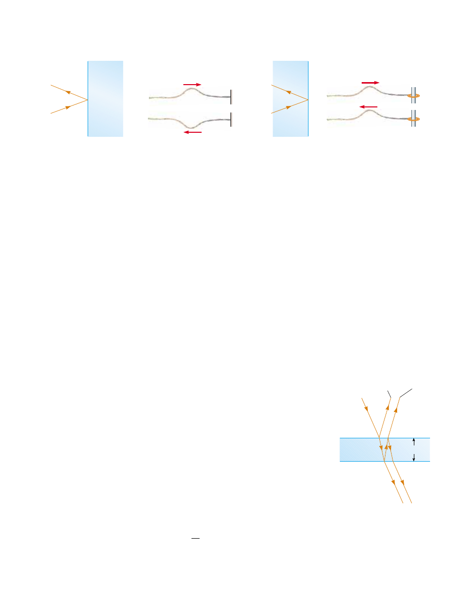
Rigid support
String analogy
180
° phase change
n
1
n
1
n
2
n
2
<
(a)
Free support
No phase change
n
1
n
1
n
2
n
2
>
(b)
Figure 37.16 (a) For n
1
2
n
2
, a light ray traveling in medium 1 when reflected from
the surface of medium 2 undergoes a 180° phase change. The same thing happens with
a reflected pulse traveling along a string fixed at one end. (b) For n
1
'
n
2
, a light ray
traveling in medium 1 undergoes no phase change when reflected from the surface of
medium 2. The same is true of a reflected wave pulse on a string whose supported end
is free to move.
No phase
change
Air
180
° phase
change
1
2
A
t
Film
Air
B
3
4
Figure 37.17 Interference in light
reflected from a thin film is due
to a combination of rays 1 and 2
reflected from the upper and lower
surfaces of the film. Rays 3 and 4
lead to interference effects for light
transmitted through the film.