KTM LC4 400-660LC42003 engine. Manual - part 15
7-27D
G
M
Ignition system
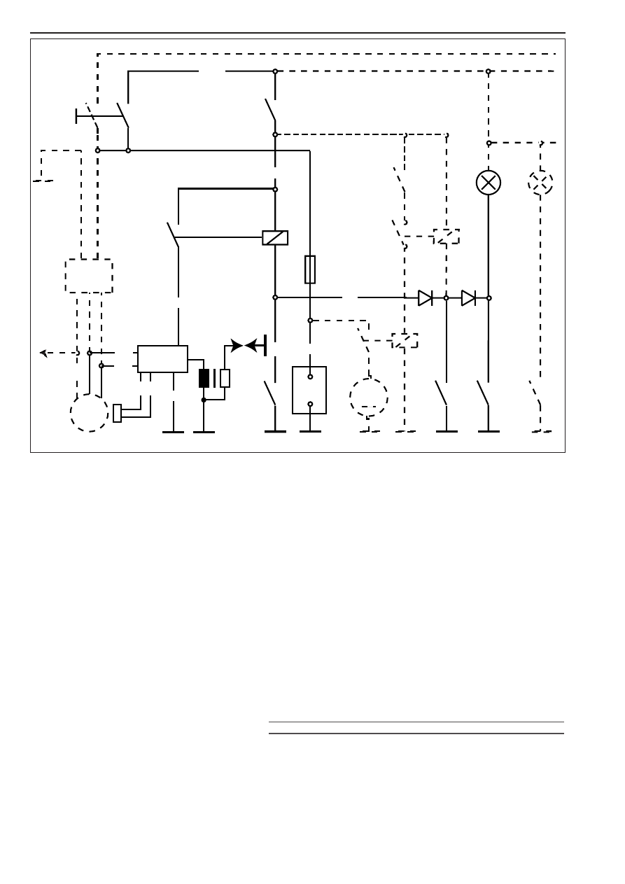
From the battery
1
the battery voltage is conducted via the main fuse
2
through the ignition lock
3
and the emergency OFF switch
4
,
which are both ON, to the side stand relay
5
.
The side stand relay conducts the battery voltage to the CDI unit
6
, if
at least one of the following requirements is met :
● The side stand is up (side stand switch closed).
● The transmission is switched to neutral (neutral switch closed).
● The clutch is pulled (clutch switch closed).
The pulse generator
7
transmits a signal to the CDI unit
6
upon every
rotation of the crankshaft. In the CDI unit, the ignition point is
computed from this signal.
The ignition pulse is transmitted to the ignition coil
8
(i.e. an ignition
spark is generated).
NOTE: The ignition system is a digital high voltage capacitor ignition
that receives its power supply from the battery. Therefore, it works only
with an intact battery.
When the battery is discharged below the threshold level, the voltage
can, due to the starting process, drop below the minimum supply
voltage required by the ignition.
!
CAUTION
!
S
AFE AND FAULTLESS OPERATION OF THE DIGITAL IGNITION REQUIRES SPARK PLUG
CONNECTORS AND SPARK PLUGS WITH INTEGRATED RESISTANCE TYPE SUPPRESSORS
.
bl . . . . . . . . .blue
br . . . . . . . . .brown
ge . . . . . . . .yellow
gr . . . . . . . . .grey
g . . . . . . . . .green
o . . . . . . . . .orange
r . . . . . . . . . .red
ra . . . . . . . . .pink
s . . . . . . . . . .black
v . . . . . . . . .violet
w . . . . . . . . .white
1
2
3
4
5
6
7
8
9
1
Battery
2
Main fuse
3
Ignition lock
4
Emergency-off switch
5
Auxiliary relay
6
CDI
7
Pulse generator
8
Ignition coil
9
Side stand switch
ge-bl
ra
s-r
r-s
r
r
0
s
w
g
ge
ra