BMW Motorcycle (R1100RT, R1100RS, R850/1100GS, R850/1100R). Manual - part 47
 

  Index      Manuals     BMW AG Motorcycle (R1100RT, R1100RS, R850/1100GS, R850/1100R). Repair Manual


Search            


Content   ..  45  46  47  48   ..


BMW Motorcycle (R1100RT, R1100RS, R850/1100GS, R850/1100R). Manual - part 47


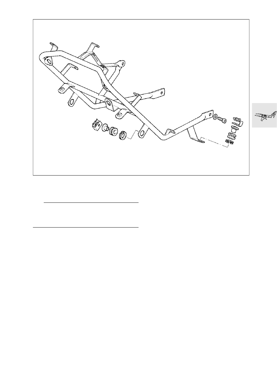
46.31

[RS] Removing and installing fairing 
holder

e

 Caution:

Switch off ignition.
Disconnect ground (earth) lead from battery.
Insulate ground (earth) lead.

•

Remove side sections of fairing.

•

Remove inner fairing panel.

•

Turn adjusting shaft counterclockwise to release 
windshield adjuster.

•

Detach instrument cluster.

•

Separate plug connectors for headlights and in-
dicators.

•

Remove top section of fairing with headlight.

•

Detach connector strip and wiring harness from 
fairing holder.

•

Detach oil cooler mount.

•

Install in the reverse order of work.

X

 Tightening torque:

Fairing support bracket to frame  ................. 20 Nm

RS460120

46.32

Removing and installing frame

•

Remove fuel tank.

•

Detach brake line from frame.

•

[RS/GS] Detach fairing holder at frame.

e

 Caution:

Fairing will drop unless held securely.
If necessary, place foam rubber or similar material 
below fairing panel.

•

Detach ball joint at front of control arm and pull 
telescopic fork forwards.

•

Detach front suspension strut at top.

•

Unscrew pin (1) from engine and remove.

•

Screw the ball joint on handtight at the front of 
the leading link.

•

Detach struts (2) from frame and loosen at 
engine.

•

[RS] Using socket wrench insert with 6 mm 
(0.2362 in) Allen key, BMW No. 31 5 600, detach 
ball joint at fork bridge.

•

[R] Detach handlebar from fork bridge.

•

[R] Pull headlight holder forwards.

•

Unfasten screw connection between fork bridge 
and frame.

L


Note:

Screw pin is a press fit in ball thrust bearing: remove 
complete unit.

•

[R] Detach oil cooler holder.

•

Remove frame.

•

Install in the reverse order of work.

X

 Tightening torque:

Frame to engine ........................................... 82 Nm
Struts to frame
(8.8 screw) ................................................... 47 Nm 
(10.9 screw) ................................................. 58 Nm 
Struts to engine
[RS] ............................................................. 47 Nm
[GS/R] ......................................................... 58 Nm
Fairing support bracket to frame .................. 20 Nm

RS460130

2

1

RS

31 5 600

46.33

[RS] Removing and installing grab 
handle/case holder

X

 Tightening torque:

Grab handle to rear frame .............................. 9 Nm

RS460140

46.34

[RS] Removing and installing rear 
fairing

•

Remove dualseat.

•

Remove rear light.

•

Remove rear fairing panel.

•

Install in the reverse order of work.

RS460040

46.35

[RS] Removing and installing 
number plate bracket

•

Remove dualseat.

•

Remove number plate bracket.

•

Install in the reverse order of work.

RS460150

46.36

[RS] Removing and installing lower 
rear section

e

 Caution:

Switch off ignition.
Disconnect ground (earth) lead from battery.
Insulate ground (earth) lead.

•

Remove dualseat.

•

Remove number plate bracket.

•

Remove rear light.

•

Remove rear fairing.

•

Remove turn indicator lenses.

•

Disconnect/detach turn indicators.

•

Detach wiring harness from lower rear section.

•

Remove dualseat lock.

•

Remove lower rear section.

•

Install in the reverse order of work.

RS460050

46.37

Removing and installing rear sec-
tion of frame

e

 Caution:

Switch off ignition.
Disconnect ground (earth) lead from battery.
Insulate ground (earth) lead.

•

Remove dualseat.

•

[RT] Remove mirrors.

•

[RT] Remove side sections of fairing.

•

Remove fuel tank.

•

[GS/RT] Remove luggage rack.

•

[GS/RT] Detach wiring harness at rear section of 
frame/detach central electrical equipment box 
only.

•

[RS/R/RT] Remove rear light.

•

[RS/R/RT] Remove rear fairing.

•

[RS/R/RT] Detach wiring harness from left turn 
indicator to central electrical equipment box/de-
tach central electrical equipment box only.

•

[RS/R/RT] Remove lower rear section.

•

[ABS] Separate the ABS sensor plug and detach 
the cable.

•

Disconnect the brake light switch plug and de-
tach the cable.

•

Disconnect the side stand switch plug and de-
tach the cable.

•

Disconnect the neutral switch plug and detach 
the cable.

•

Detach diagnosis plug and cable.

•

Pull brake cable out of holder/rear section of 
frame.

•

Pull brake fluid container out of holder.

•

Detach muffler (silencer) from rear section of 
frame.

•

Detach upper suspension strut mount.

•

[RT] Detach footrest plates from rear section of 
frame.

•

Remove air cleaner box from rear section of 
frame.

•

Remove rear section of frame.

•

Remove fittings.

•

Install in the reverse order of work.

Tightening sequence:
1. Screw connection  ................ on right of gearbox
2.  ............................................... on right of engine
3.  ..................................................on left of engine
4.  ............................................... on left of gearbox

X

 Tightening torque:

Rear section of frame to gearbox/engine ..... 47 Nm

RS

2

1

3

4

RS460160

46.38

[RS] Removing and installing center 
stand

•

Remove lower section of fairing.

2

1

2

3

1

2

v

2701

v

2701

v

2701

v

2701

v

2701

RS460030


Content   ..  45  46  47  48   ..