BMW Motorcycle (R1100RT, R1100RS, R850/1100GS, R850/1100R). Manual - part 36
 

  Index      Manuals     BMW AG Motorcycle (R1100RT, R1100RS, R850/1100GS, R850/1100R). Repair Manual


Search            


Content   ..  34  35  36  37   ..


BMW Motorcycle (R1100RT, R1100RS, R850/1100GS, R850/1100R). Manual - part 36


33.17

•

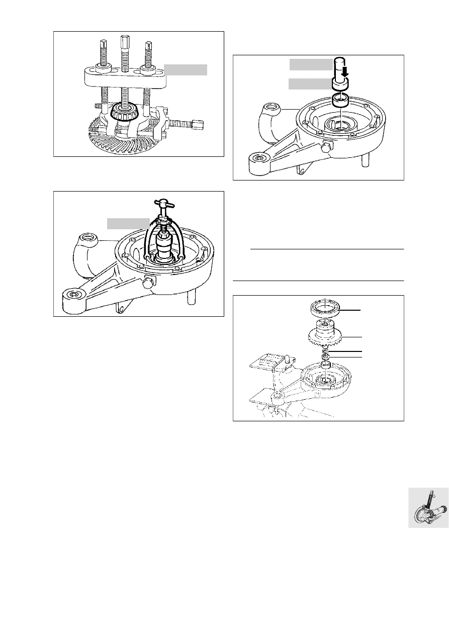
Using puller, BMW No. 00 7 500, pull taper roller 
bearing off crown wheel.

•

Pull out the outer race using internal puller, 
BMW No. 00 8 560.

Installing crown wheel

•

Heat the housing to 80 °C.

•

Insert the outer race in the bearing seat with drift, 
BMW  No. 33 1 880, and handle,  
BMW  No. 00 5 500
.

•

Check that outer race is correctly fitted by strik-
ing gently.

L

 Note:

If new parts are installed (e.g. taper roller bearing), 
check tooth backlash and adjust if necessary.

•

Place the existing spacer ring (1) on the crown 
wheel.

•

Heat taper roller bearing (2) to 80 °C and push it 
on.

•

Install crown wheel (3).

•

Heat deep-groove ball bearing (4) to 80 °C and 
place it in position.

00 7 500

LT330140

00 8 560

LT330150

00 5 500

33 1 880

LT330160

1

2

3

4

RT330170

33.18

Checking/adjusting backlash

•

Place measuring fixture (1), BMW No. 33 2 600, 
with dial gauge on the crown wheel and secure 
to housing with knurled screw (2).

•

Attach measuring arm (3), BMW No. 33 2 604, 
centrally to crown wheel

•

With the palm of the hand, press the crown wheel 
into the housing and turn to and fro to check 
tooth backlash.

L

 Note:

Check tooth backlast at three points 120 degrees 
apart; turn the bevel pinion with the crown wheel.

•

Compensate for excessive backlash by inserting 
a thinner shim washer, and for insufficient back-
lash by inserting a thicker shim washer (1).

Backlash:
(adjusting without oil)....................... 0.07...0.16 mm

.............................................. (0.00276...0.0063 in)

33 2 604

33 2 600

1

2

3

RT330190

90°

RT330200

1

RT330210

33.19

Checking tooth contact pattern

•

The tooth contact pattern must be checked if the 
gear set, housing or input bevel pinion bearing 
have been renewed

L

 Note:

The contact pattern is adjusted at the shim washer 
(1) on the input bevel pinion.

•

Degrease the tooth flanks on crown wheel and 
pinion, and coat with engineer’s blue.

•

Insert the crown wheel, press into housing with 
the palms of the hands and turn to and fro.

•

If the correct spacer disc is installed, the follow-
ing contact pattern appears when no load is ap-
plied.

L

 Note:

The contact point is central on front flank V.
The contact point is closer to the larger diameter on 
back flank R.

e

 Caution:

Teeth should never make contact at the smaller di-
ameter.

•

If this contact pattern is obtained, a thinner shim 
washer must be installed.

•

If this contact pattern is obtained, a thicker shim 
washer must be installed.

1

LT330220

V

R

LT330230

LT330240

LT330250

33.20

Shimming housing cover

•

To obtain the correct roller bearing preload, the 
housing cover must be shimmed

•

Using depth gauge,  BMW No. 00 2 550, meas-
ure distance a.

•

Place measuring ring, BMW No. 33 2 601, in po-
sition and secure.

•

Measure from the outer ball bearing race through 
the cutout in the measuring ring to the housing 
joint face and determine distance b.

•

Distance a – distance b = shim thickness (without 
preload).

•

Apply a light coat of grease to the selected shim 
washer, and install it.

Preload:......... 0.05...0.1 mm (0.00197...0.03937in)

Installing housing cover

•

Using drift,  BMW No. 33 1 860, and handle, 
BMW No. 00 5 500, drive in the sealing ring.

•

Install O-ring and apply a light coat of oil/grease.

•

Heat housing cover to 80 °C/install. 

•

Tighten retaining bolts in a crosswise pattern

•

X

 Tightening torque:

Housing cover.............................................. 35 Nm

Installing splined element

•

Coat splines on input pinion with 
Staburags NBU 30 PTM.

•

Fit sliding element to drive pinion.

•

Locate retaining ring with gentle blows (plastic 
hammer).

00 2 550

a

LT330260

33 2 601

b

LT330270

00 5 500

33 1 860

LT330280

33.21

Installing rear wheel drive

•

Coat splines at sliding element (arrow) with 
Staburags NBU 30 PTM.

•

Apply a small amount of grease to the inner race 
(1, 2) of the left needle roller bearing and install it.

•

Install rear wheel drive with gaiter; insert sliding 
section into drive shaft.

e

 Caution:

Support the rear wheel drive.

•

Screw in fixed bearing journal (3) using Loctite.

e

 Caution:

The inner race must never press against the ends of 
the needles.

•

Apply Loctite to the entire length of the thread 
on free bearing pin (4), and screw it in.

•

Tighten fixed bearing of swinging arm.

X

 Tightening torque:

Fixed bearing journal
(thread cleaned + Loctite 2701).................. 150 Nm

e

 Caution:

When threaded connections are made with the aid 
of Loctite 2701, they must be tightened to their final 
torque without delay.
The Loctite hardening time is at least 3 hours.

L

 Note:

Use an acetone-based cleaning agent, e.g.
Loctite Rapid Cleanser 706
Loctite Order No. 70636-AC

•

Tighten idler bearing for swinging arm.

X

 Tightening torque:

Free bearing journal 
(thread cleaned + Loctite 2701 applied to complete
löength of thread on free bearing pin)............. 7 Nm
Locknut...................................................... 105 Nm

1

4

6

5

2

3

v

v

2701

2701

LT330011

33.22

•

Apply a weight of approx. 85 kg to the motorcy-
cle and tighten the strut (5) previously 
loosened.

X

 Tightening torque:

Reaction link to rear wheel drive................... 43 Nm

•

Tighten clamping strap (6) on gaiter.

•

If necessary, fill with oil.

Fill quantity:
Initial filling............................0.25 l (0.44 Imp. pints)
During oil changes .............0.23 l (0.405 Imp. pints)

Oil grade:
Brand-name hypoid gear oil, SAE 90, API class 
GL 5

•

[ABS]/[RS/R/RT] Install the brake disc in the 
previously marked position.

•

Install the rear wheel.

•

Install brake caliper.

e

 Caution:

Do not damage brake pads; do not tilt when 
installing.

•

[GS/R/RT]/[ABS] Install the sensor.

•

[ABS] Check that sensor gap is correct.

ABS rear sensor gap: ....................0,45...0,55 mm 

.............................................. (0.0177...0.02165 in)

•

[RS] Install the number plate holder.

•

[GS] Install the rear wheel cover.

33.23

Removing, dismantling, reassem-
bling and installing rear swinging 
arm

Removing rear swinging arm

•

Unfasten suspension strut mount (1).

•

[RT] Detach brake master cylinder from right 
footrest plate.

•

[RT] Detach gear shift linkage from left footrest 
plate.

•

[RT] Remove right and left footrest plates.

•

Heat free swinging arm bearing (2) to max. 
120 °C/loosen. 

•

Heat fixed swinging arm bearing (3) to max. 
120 °C/unscrew.

•

Unfasten free swinging arm bearing

Removing and installing taper roller 
bearing

•

Using counter-support,  BMW No. 00 8 572, and 
internal puller 21/2, BMW No. 00 8 571, pull out 
taper roller bearing.

•

Pull out outer race with internal puller 21/5, 
BMW No. 00 8 563.

•

To install the bearing, heat the swinging arm to 
80 °C.

1

2

3

j

120

j

120

RS330031

00 8 572

00 8 563

00 8 571

LT330370

33.24

Removing and installing flexible gaiter

•

Remove inner retaining ring; remove gaiter from 
swinging arm.

•

When installing, coat inner and outer sealing lips 
(arrows) with Staburags NBU 30 PTM.

e

 Caution:

Drive shaft clearance when suspension is com-
pressed: aperture in retaining ring must be 
horizontal.

Removing drive shaft

•

Press off drive shaft.

e

 Caution:

Do not scratch painted components: if necessary, 
use a rubber mat.

Checking universal joint for wear

•

Determine end float and face runout.

Installing drive shaft

•

Coat the splines on the output shaft with 
Staburags NBU 30 PTM.

•

Fit drive shaft to output shaft.

•

Engage the snap ring with gentle blows (plastic 
hammer).

LT330300

RS330040

LT330420


Content   ..  34  35  36  37   ..