BMW Motorcycle (R1100RT, R1100RS, R850/1100GS, R850/1100R). Manual - part 33
 

  Index      Manuals     BMW AG Motorcycle (R1100RT, R1100RS, R850/1100GS, R850/1100R). Repair Manual


Search            


Content   ..  31  32  33  34   ..


BMW Motorcycle (R1100RT, R1100RS, R850/1100GS, R850/1100R). Manual - part 33


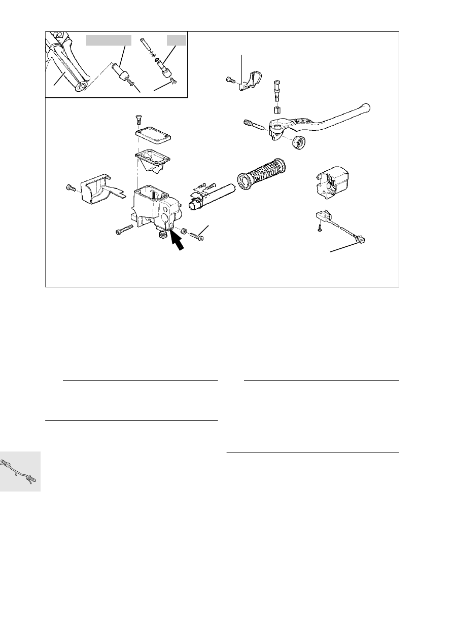
32.8

Removing and installing right 
handlebar fitting

•

[RS] Remove left side trim.

•

[GS/R] Detach fuel tank and pull it to the rear.

•

[RT] Remove upper section of fairing.

•

Separate connector (1) at brake light switch.

•

Detach brake line and seal off.

e

 Caution:

Do not allow brake fluid to come into contact with 
painted parts of the motorcycle, because brake fluid 
destroys paint.

•

Remove combination switch.

•

Unfasten throttle cable cover (2) and disconnect 
throttle cable.

•

Unfasten screw (3) and pull out handlebar 
weight.

With heated handlebar grips

•

Fold back rubber grip at handlebar fitting end.

•

Unfasten retaining screws for heated handlebar 
grip.

•

Separate connector to heated handlebar grip.

•

Unfasten cable shoes at connector.

•

Pull lead through handlebar.

Without heated handlebar grips 

•

Cut open rubber grip (4) and pull off.

•

Unfasten clamp screw (5) from fitting housing. 

•

Remove handlebar fitting.

•

Install in the reverse order of work.

•

Align slot of handlebar fitting (arrow) with punch-
mark on handlebar.

•

Secure rubber handlebar grip with 
Loctite 638 adhesive and surface activator.

e

 Caution:

Top up brake fluid, bleed brake system. 
– Adjustable handlebar – In the center position the 
brake hose fitting at the master brake cylinder must 
have sufficient clearance 
(app. 5 ... 10 mm (0.1969...0.3937in)) 
from the center section of the handlebar. 
If necessary, unfasten the wiring harness.

X

 Tightening torque:

Brake hose to fitting ....................................... 7 Nm

1

2

5

4

3

RS

GS/R/RT

GS320020

32.9

[RS] Removing and installing 
handlebar

•

Remove left/right handlebar fittings.

•

Remove trim (1) from fork bridge (press hooks in 
direction of arrow).

•

Remove handlebar.

•

Install in the reverse order of work.

e

 Caution:

Ensure that brake hoses are correctly located.

X

 Tightening torquet:

Handlebar at rubber mount  ......................... 40 Nm
Rubber mount at fork bridge ........................ 40 Nm
Handlebar weight to fixed handlebar ............ 20 Nm
Handlebar weight to adjustable handlebar
(clean thread + Loctite 2701).......................... 7 Nm

1

RS320030

32.10

[GS/R/RT] Removing and installing 
handlebar

•

Remove left/right handlebar fittings.

•

Remove handlebar.

•

Install in the reverse order of work.

e

 Caution:

Make sure that brake hoses are correctly routed.
[GS] Align punch mark on handlebar with gap be-
tween clamp blocks.

X

 Tightening torque::

Clamp to fork bridge
[GS] ............................................................. 21 Nm
Handlebar to fork bridge
[R/RT].......................................................... 21 Nm
Weight to handlebar ..................................... 20 Nm

GS

R/RT

GS320030

32.11

Removing and installing wire cable 
distributor block

•

[RS/RT] Remove side fairings.

•

Unscrew fuel tank and pull to the rear.

•

Remove cold-start lever (increased idle speed)/
disconnect the wire cable.

•

Remove the cable cover at the throttle operating 
fitting.

•

Detach the wire cables at the left and right 
throttle stub pipes.

•

Relesse the cable straps.

•

Detach the engine breather pipe (1) from the en-
gine.

•

Pull the wire cable distributor block (2) out of 
holder (3) in the direction of the arrow.

•

Install in the reverse order of work.

•

Adjust the wire cables.

a

See Group 00

1

3

2

RT320120

32.12

Removing and installing throttle 
cable

•

[RS] Remove left side fairing.

•

[GS/RT] Detach fuel tank and pull it to the rear.

•

Remove cable cover (1) from handlebar fitting 
and disconnect cable.

•

Unfasten cable adjusting screw (2) on the right 
throttle body.

•

Press in retaining spring (3) and disconnect ca-
ble.

•

Unfasten both cable adjusting screws (4) on left 
throttle body

•

Press in retaining spring (5) and disconnect 
cable

•

Install in the reverse order of work.

e

 Caution:

Install wire cable without kinking.

•

Adjust wire cable.

a

See Group 00

1

RS320041

2

GS320110

3

4

4

5

RS320050

32.13

With wire cable distribution block

•

Remove cable cover (1) at fitting/disconnect the 
cable.

•

Remove the choke lever/disconnect the cable.

•

Remove the wire cable adjusting screws (2) at 
the right and left throttle stub pipes.

•

Press in retaining spring (3) and disconnect the 
cables.

•

Pull out the cable distribution block (6) in the di-
rection of the arrow.

•

Release the keeper (7) and remove the distribut-
ing disk (8).

•

Disconnect cables (9), (10) and (11).

•

Install in the reverse order of work.

•

Adjust the wire cables.

a

See Group 00

8

7

6

9

10

11

RT320130

32.14

Removing and installing cold-start 
cable

•

[RS/RT] Remove the left fairing.

•

[GS] Detach the fuel tank and pull it to the rear.

•

Remove actuating lever (1)/disconnect cable

•

Slacken off cable adjustment screw (2) on left 
throttle body

•

Press in retaining spring (3) and disconnect 
cable.

•

Install in the reverse order of work..

e

 Caution:

Install wire cable without kinking.

•

Adjust wire cable.

a

See Group 00

With wire cable distribution block

•

Remove cable cover at throttle fitting/disconnect 
the cable.

•

Remove actuating lever (1)/disconnect cable.

•

Remove the cable adjusting screws at the right 
and left throttle stub pipes.

•

Press in the retaining spring and remove the 
cable

•

Remove the wire cable distribution block (4) in 
the direction of the arrow.

•

Detach cable (5).

•

Install in the reverse order of work.

•

Adjust wire cable

a

See Group 00

1

RS320060

RS320070

2

3

4

5

RT320130

32.15

Removing and installing clutch 
cable

•

Remove right side trim.

•

[RT] Detach fuel tank and pull it to the rear.

•

Disconnect clutch cable from release lever/gear-
box.

•

Disconnect clutch cable from handlebar lever.

•

Install in the reverse order of work.

e


Caution:

Install wire cable without kinking.

•

Adjust wire cable.

a

See Group 00

RS320081

RS320091


Content   ..  31  32  33  34   ..