BMW Motorcycle (R1100RT, R1100RS, R850/1100GS, R850/1100R). Manual - part 28
 

  Index      Manuals     BMW AG Motorcycle (R1100RT, R1100RS, R850/1100GS, R850/1100R). Repair Manual


Search            


Content   ..  26  27  28  29   ..


BMW Motorcycle (R1100RT, R1100RS, R850/1100GS, R850/1100R). Manual - part 28


23.24

•

Clamp splined end of input shaft in vice fitted 
with jaw protectors.

•

Relieve strain on locking ring (1), if necessary 
lightly tap bearing inner ring to release.

•

Remove locking ring and washer (1/ 2).

•

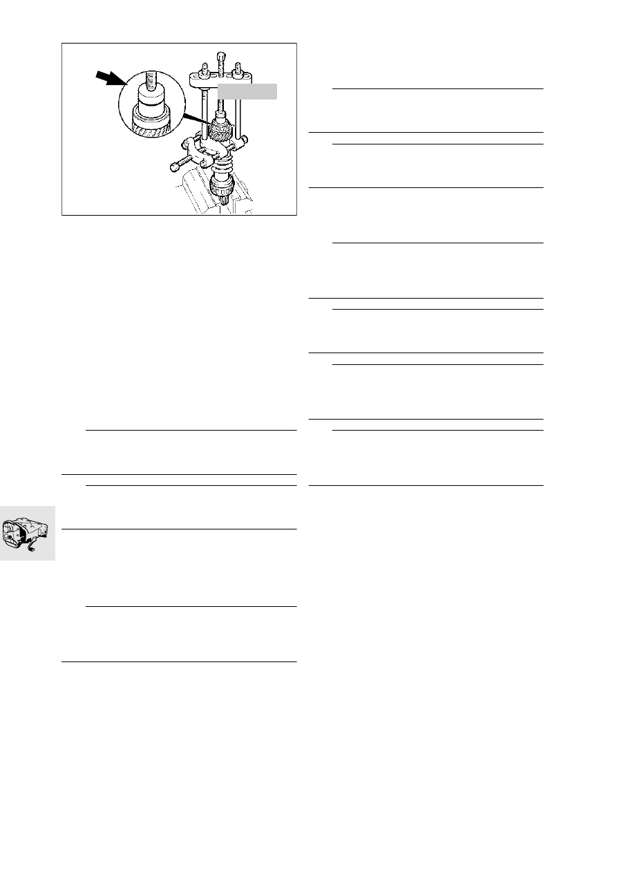
Using universal puller, BMW No. 00 7 500, and 
thrust adapter (arrow) to apply uniform pressure, 
remove spur gear (4) complete with bearing (3).

•

Remove washer (7), spring (6), thrust piece (5) 
and spur gear (4).

•

Remove bearing (8) in the same way.

•

Slip washer (7) into position with bevel facing 
away from the spring. 

•

Slip spring (6), thrust piece (5) and spur gear (4) 
onto shaft.

•

Press on bearing (3) cold, using press, or heat to 
80 °C and position on input shaft.

e

 Caution:

If necessary, drive further on by striking inner race 
only.

e

 Caution:

Be careful of the sealing washer as you heat the 
bearing (Clean Bearing); risk of damage.

•

Install spacer (2).

•

Install locking ring (1) and make sure that assem-
bly is free of play.

•

Position universal puller under spur gear and 
seat bearing against locking ring

e

 Caution:

In order to avoid measuring errors when shims are 
subsequently installed, make sure that there is no 
clearance between bearing and locking ring.

•

Press on grooved ball bearing (8) cold, using 
press, or heat to 80 °C (176 °F) and position on 
input shaft..

e

 Caution:

If necessary, drive further on by striking inner race 
only.

e

 Caution:

Be careful of the sealing washer as you heat the 
bearing (Clean Bearing); risk of damage.

•

By preference, press on grooved ball bearing (8) 
cold, using press, or alternatively heat to 80 °C 
(176 °F) and position on input shaft.

L

 Note:

If input shaft has to be shimmed, do not install 
grooved ball bearing (8) until all measurements have 
been completed.

e

 Caution:

Be careful of the sealing washer as you heat the 
bearing (Clean Bearing); risk of damage.

e

 Caution:

When seating components on the input shaft while 
removed from engine, apply pressure to the inner 
ring only.

e

 Caution:

If the Clean Bearing input shaft is installed, do not 
strike shaft/bearing as otherwise, the bearing might 
no longer be correctly seated on the locking ring.

00 7 500

Clean Bearing

RT230161

23.25

Dismantling/reassembling output shaft 

•

[1993 model year] When determining total dis-
tance G, include spacing washer (1); if neces-
sary, adjust distance G with shims.

•

[from 1994 model year] Measurement and ad-
justment of G are no longer needed.

Removing deep-groove ball bearing

•

Clamp the output shaft into a vise with soft jaws.

•

Using universal puller, BMW No. 00 7 500, and 
pressure head, pull off the deep-groove ball 
bearing.

1

G=125,8

-0,1

RS230191

00 7 500

RS230192

23.26

Removing spur gears

•

Remove spur gear for 1st (1) and 5th gear (2) with 
thrust washers.

•

Remove thrust washer (4) and bearing bushing 
(3) with spur gear for 3rd gear (5).

•

[from 1994 model year on] take off the O-ring 
(15).

•

Remove spacer (7) and bearing bushing (6) with 
spur gear for 4th gear (8).

•

Remove retaining ring (9).

•

Remove toothed disk (10).

•

Remove spur gear for 2nd gear (11).

•

Remove split needle cage (12).

•

Remove toothed disk (13) and retaining ring (14).

•

[from 1994 model year on] Take off O-ring (16).

1

6

15

7

8

3

4

5

2

RS230193

3

4

5

RS230194

16

14

13

12

11

10 9

RS230195

23.27

Installing spur gears

•

Slide toothed disk (13) up to front of bearing seat.

•

Slide on retaining ring (14) and locate in groove.

•

[from 1994 model year on] Push O-ring (16) 
onto seat.

e

 Caution:

Use a new O-ring.

•

Fit split needle cage (12) to output shaft.

•

First slide spur gear for 2nd gear (11) over needle 
cage, with apertures at top.

•

Install toothed disk (10), then retaining ring (9).

•

Clamp output shaft into vise with soft jaws; the 
drive shaft splines must face upwards.

•

Slide spur gear for 3rd gear (5) onto output shaft 
with apertures facing upwards.

•

Fit thrust washer.

•

Heat the wide race (3) to 80 °C and push it onto 
the output shaft as far as the support washer.

•

Fit spur gear for 5th gear (2) with dogs facing 
downwards.

•

Fit thrust washer.

•

Press on grooved ball bearing cold, using press, 
or heat to 80 °C and position on input shaft.

e

 Caution:

If necessary, drive further on by striking inner race 
only.

e

 Caution:

Be careful of the sealing washer as you heat the 
bearing (Clean Bearing); risk of damag.

14 13

12

11

10

9

16

RS230195

2

5

RS230198

23.28

•

Invert output shaft in vise with spline tracks fac-
ing downwards.

•

Slide spur gear for 4th gear (8) onto output shaft 
with dogs facing downwards.

•

Fit spacer (7).

•

[from 1994 model year on] Push O-ring (15) 
onto seat.

e

 Caution:

Use a new O-ring.

•

[1993 model year] Measure distance G and 
shim as necessary.

•

[1993 model year] Heat the narrow race (6) to 
80 °C and push it onto the output shaft as far as 
the spacing washer.

•

[from 1994 model year on] Heat the narrow race 
(6) to 80 °C and push it on flush with the step in 
the shaft.

•

Slide spur gear for 1st gear (1) onto output shaft 
with aperture and shift teeth facing downwards.

•

Fit thrust washer.

•

Press on grooved ball bearing cold, using press, 
or heat to 80 °C and position on input shaft.

e

 Caution:

If necessary, drive further on by striking inner race 
only.

e

 Caution:

Be careful of the sealing washer as you heat the 
bearing (Clean Bearing); risk of damage

.

1

6

7 8

15

j

80

RS230190

G=125,8

-0,1

RS230199

23.29

Installing gearbox shafts

L

 Note:

If the input shaft has to be shimmed, do not install 
the input-side bearing until all measurements have 
been completed.

•

Heat the output shaft bearing point to 100 °C.

•

[1993 model year] First insert the input shaft (1).

•

Push sliding sleeve (2), BMW No. 23 4 622, onto 
the output shaft.

•

[1993 model year] Insert the idler shaft and out-
put shaft (3) into the gearbox housing together.

•

[Clean Bearing] Install spacer (5).

a

page 23.22

•

[from 1994 model year on] Insert the input, idler 
and output shafts into the gearbox housing to-
gether.

•

With gentle blows of a plastic-faced hammer, 
check that bearing is firmly seated.

e

 Caution:

Do not strike the seat of a Clean Bearing shaft, as 
otherwise the bearing might no longer be correctly 
seated on the locking ring.

•

Install oil baffle plates (4).

e

 Caution:

After installation of the oil baffle plates, turn the 
gears and check for ease of movement..

X

 Tightening torque:

Oil baffle plate retaining screws
(clean thread + Loctite 573, also apply Loctite 573 
to the sealing face on the oil baffle plate where it 
contacts the gearbox housing) ....................... 9 Nm

3

1

23 4 622

4

2

j

100

v

v

Clean Bearing

Clean Bearing

5

RT230201

23.30

Removing and installing output shaft 
seal

•

Force out shaft seal with drift, working from the 
inside

•

Drive in the new shaft seal with drift and sliding 
sleeve, BMW No. 23 4 620.

23 4 620

RS230210

23.31

Installing selector shaft

•

Insert selector shaft with sliding sleeve (1),
 BMW  No. 23 4 612.

L

 Note:

Note washer (2).

•

[RT/GS] Attach gear shift pedal (1) horizontally, 
making sure that distance A is correct.

Distance A:.......... 51.9 ±1.8 mm (2.043 ±0.07 mm)

•

[RS/R] Attach gear shift pedal (1) horizontal, not-
ing distance B.

Maß „B“: .............. 61.2 ±1.8 mm (2.409 ±0.07 mm)

X

 Tightening torque:

Gear shift pedal.............................................. 9 Nm

23 4 612

23 4 612

2

1

RS230230

A

1

RT230330

B

1

RS230340


Content   ..  26  27  28  29   ..