BMW AG Motorcycle (R 850 C, R 1200 C). Manual - part 17
 

  Index      Manuals     BMW AG Motorcycle (R 850 C, R 1200 C). Repair Manual


Search            


Content   ..  15  16  17  18   ..


BMW AG Motorcycle (R 850 C, R 1200 C). Manual - part 17


23.14

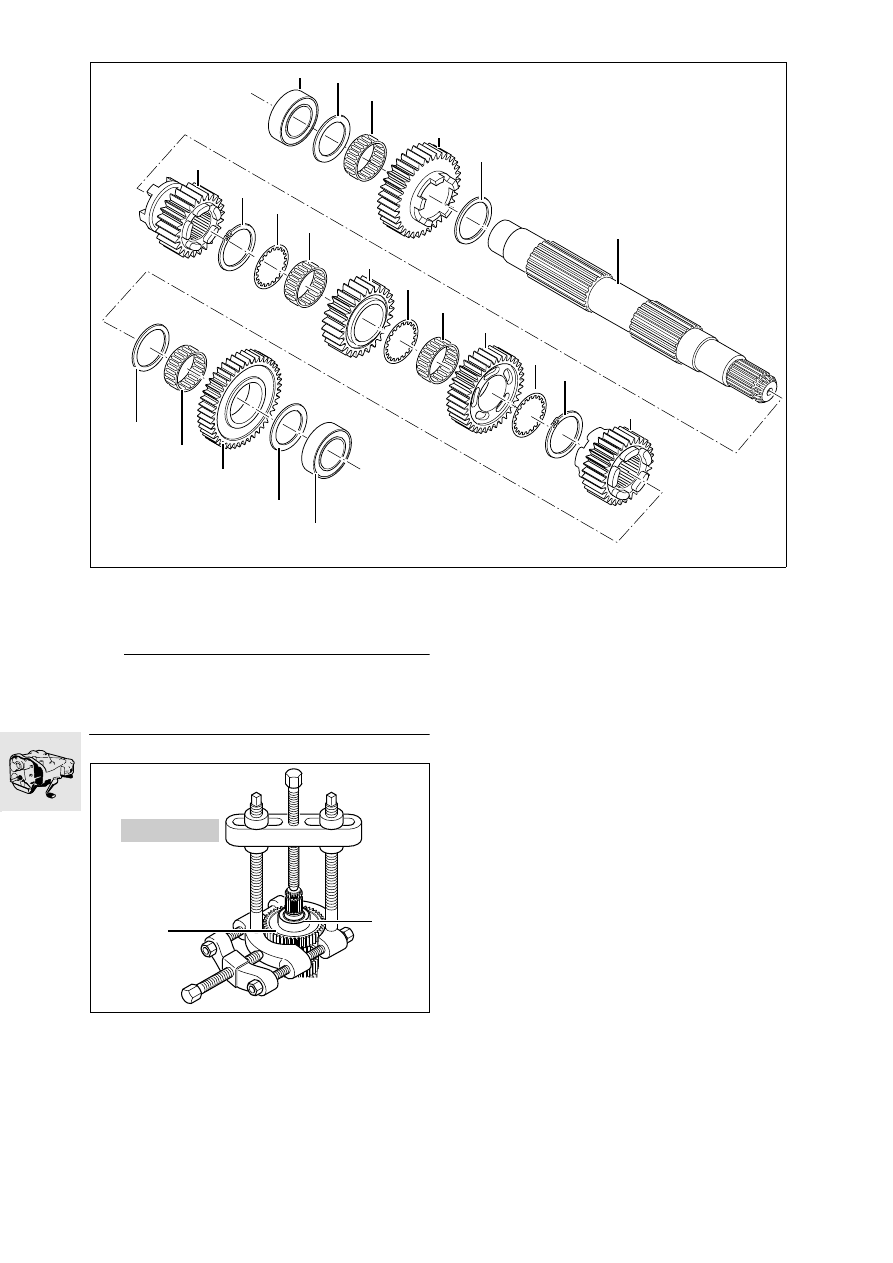
Dismantling/reassembling output shaft

Stripping down output shaft

e

 Caution:

To avoid damaging the needle roller bearing at the 
splines, open it out carefully at the joint line before 
removing. 

•

Using universal puller, BMW No. 00 7 500, pull 
off deep-groove ball bearing (22) together with 
1st gear wheel (20).

•

Remove spacing washer (21), shift gear wheel for 
1st gear (20), needle roller bearing (19) and 
spacing washer (18).

•

Remove sliding gearwheel (7).

•

Remove circlip (8), support washer (9), shift 
gearwheel for 3rd gear (10) and needle roller 
bearing (11).

•

Remove support washer (12), 4th gear shift 
wheel (13), needle roller bearing (14) and support 
washer (15).

•

Remove circlip (16) and sliding gearwheel for 
5th gear (17).

•

Turn output shaft (6) and clamp into the vise with 
soft jaws.

•

Using universal puller, BMW No. 00 7 500, pull 
off deep-groove ball bearing (1) together with 
shift gearwheel for 2nd gear (4).

•

Remove shim washer (2), needle roller bearing (3), 
shift gearwheel for 2nd gear (4) and thrust wash-
er (5).

KR230100

1

3

4

5

6

7

8

9

10

11

12

13

14

15

16

17

18

19

20

21

22

2

00 7 500

KR230110

22

20

23.15

Assembling output shaft

L

 Note:

Assembly starts at the shift gearwheel for 4th gear. 
Before assembly, oil all running surfaces lightly with 
gear oil.

•

Clamp the output shaft into the vise with soft 
jaws and with the splines facing upwards.

•

Install circlip (16/arrow).

•

Install thrust washer (15).

•

Install needle roller bearing (14).

e

 Caution:

To avoid damaging the needle roller bearing at the 
splines, spread it carefully at the butt joint before in-
stalling. 

•

Install shift wheel for 4th gear (13) with the pock-
ets facing circlip (16). 

•

Install support washer (12) and needle roller (11).

•

Install shift wheel for 3rd gear (10) with pockets 
facing away from the 4th gear shift wheel (13).

•

Install support washer (9) and circlip (8).

•

After installing the 3rd and 4th shift gearwheels, 
measure endplay (

a 

23.16).

•

Install sliding gear (7) with the recess for the se-
lector fork facing the shift gearwheel for 3rd gear 
(10).

•

Install support washer (18) and needle roller 
bearing (19).

•

Install the shift gearwheel for 1st gear (20) with 
the pockets facing sliding gearwheel (7).

•

Install spacing washer (21) and deep-groove ball 
bearing (22).

•

After installing, check endplay at the shift gear-
wheel for 1st gear (

a 

23.16).

KR230120

21

20

19

18

16

15

14

13

12

11

10

9

8

7

6

1

2

3

4

5

17

22

5th gear

2nd gear

4th gear

3rd gear

1st gear

KR230130

16

6

23.16

•

Transfer output shaft (6) to new position in vise.

•

Install shift wheel for 5th gear (17) with the recess 
for the selector fork facing the 2nd gear shift 
wheel (3).

•

Install support washer (5) and needle roller bear-
ing (4).

•

Install the shift wheel for 2nd gear (3) with the 
dogs facing the 5th gear shift wheel (17).

•

Check/adjust the fully-compressed length
(

a 

23.19).

•

Install spacing washer (2) of the determined 
thickness, and press on deep-groove ball bear-
ing (1).

•

Check endplay at 2nd (

a 

23.16).

Checking endplay

•

Attach dial gauge, BMW No. 00 2 510, to dial 
gauge stand.

•

Apply the dial gauge to the edge of the gear-
wheel and check endplay.

e

 Caution:

If endplay is beyond the permitted tolerances, this 
indicates either an assembly error or wear in the 
needle roller bearings, the support or spacing wash-
ers or the shift gear.
Check for wear and renew the affected parts.

Endplay values:
Endplay, 1st gear .. 0.1…0.33 mm (0.004…0.013 in)
Endplay,
2nd gear ............... 0.1…0.33 mm (0.004…0.013 in)
Endplay, 3rd/4th gear 
(total play).............. 0.1…0.67 mm (0.004…0.026 in)

KR230140

6

0

10

20

30

40 50 60

70

80

90

100

KR230150

00 2 510

23.17

Checking/adjusting fully compressed 
length of gearbox shafts and selector 
drum

Checking/adjusting fully-compressed length of 
intermediate shaft 

e

 Caution:

To adjust and check the fully-compressed length, 
measure deviation from zero as described below 
and adjust with a shim washer.
Before each measurement, even if the shaft is not 
being installed, make sure that the deep-groove ball 
bearing is fully compressed.

•

Pull off the input-side deep-groove ball bearing 
with universal puller, BMW No. 00 7 500.

•

Take off the spacing washer.

•

Insert zero gauge, BMW No. 23 4 763, into 
measuring stand, BMW No. 23 4 761.

•

Secure dial gauge, BMW No. 23 4 762, in rear 
mounting hole on measuring stand, 
BMW No. 23 4 761, and set to 0.2 mm (0.008 in) 
preload.

•

Using the dial gauge, zero to dimension “A” of 
the zero gauge, BMW No. 23 4 763.

•

Remove the zero gauge from the measuring fix-
ture.

•

Place measuring disc, BMW No. 23 4 765, on 
the intermediate shaft.

•

Place deep-groove ball bearing on measuring 
disc.

•

Insert intermediate shaft in measuring stand. 

•

Using dial gauge, measure deviation from zero of 
dimension “B” at inner bearing race. 

The deviation from zero is equivalent to the thick-
ness “C” of spacing washer (1).

•

Place a spacing washer (1) of the thickness just 
determined on the inner bearing race and check 
deviation from zero.

A = B + C

e

 Caution:

The maximum permitted deviation from zero must 
not be exceeded.

•

Remove the intermediate shaft from the measur-
ing fixture.

•

Take off spacing washer, the deep-groove ball 
bearing and the measuring disc.

•

Place a spacing washer (1) of the determined 
thickness on the intermediate shaft and press on 
the deep-groove ball bearing.

Adjusting dimensions for intermediate shaft:
Maximum deviation
from zero .........  -0.05 mm (0.002 in) … 0.00 mm/in
Fully-compressed 
length.........  198.95…199.00 mm (7.833…7.835 in)

0

90

10

20

30

40

50

60

70

80

0

90

10

20

30

40

50

60

70

80

0

90

10

20

30

40

50

60

70

80

C230051

23 4 763

23 4 761

23 4 762

23 4 765

0.2 (0.004 in)

1

3

2

1

C

B

A

23.18

Checking/adjusting fully-compressed length of 
output shaft 

e

 Caution:

To check and adjust the fully-compressed length, 
measure deviation from zero as described below 
and adjust with a shim washer.
Before each measuring step, even if the shaft is not 
to be installed, make sure that the deep-groove ball 
bearing is fully compressed.

•

Pull off output-side deep-groove ball bearing 
with universal puller, BMW No. 00 7 500.

•

Take off the spacing washer.

•

Insert zero gauge, BMW No. 23 4 763, in to 
measuring stand, BMW No. 23 4 761.

•

Secure dial gauge, BMW No. 23 4 762, in rear 
mounting hole on measuring stand, 
BMW No. 23 4 761, and set to 0.2 mm 
(0.008 in) preload.

•

Using the dial gauge, zero to dimension “A” of 
the zero gauge, BMW No. 23 4 763.

•

Remove the zero gauge from the measuring fix-
ture.

•

Place the measuring disc, BMW No. 23 4 766, 
on the output shaft.

•

Place the deep-groove ball bearing on the meas-
uring disc.

•

Insert the output shaft into the measuring stand. 

•

Using the dial gauge, measure the deviation from 
zero of dimension “B” at the inner bearing race. 

The deviation from zero represents thickness “C” of 
spacing washer (1).

•

Place spacing washer (1) of the thickness just 
determined on the inner bearing race, and check 
deviation from zero. 

A = B + C

e

 Caution:

The maximum deviation from zero must not be ex-
ceeded.

•

Remove output shaft from measuring fixture.

•

Take off spacing washer, deep-groove ball bear-
ing and measuring disc.

•

Place a spacing washer (1) of the determined 
thickness on the output shaft and press on the 
deep-groove ball bearing.

Output shaft adjusting dimensions:
Maximum deviation
from zero .........  -0.05 mm (0.002 in) … 0.00 mm/in
Fully-compressed 
length.........  192.95…193.00 mm (7.596…7.598 in)

0

90

10

20

30

40

50

60

70

80

0

90

10

20

30

40

50

60

70

80

0

90

10

20

30

40

50

60

70

80

KR230300

23 4 763

23 4 761

23 4 762

23 4 766

0.2

1

3

2

1

C

B

A

23.19

Checking/adjusting fully-compressed length of 
input shaft 

e

 Caution:

To adjust and check the fully-compressed length, 
deviation from zero must be measured as described 
below, and adjusted by means of a shim washer.
Make sure before each measuring step, even if the 
shaft is not being installed, that the deep-groove ball 
bearing is fully compressed.

•

Pull off output-side deep-groove ball bearing 
with universal puller, BMW No. 00 7 500.

•

Take off the spacing washer.

•

Insert zero gauge, BMW No. 23 4 763, into 
measuring stand, BMW No. 23 4 761.

•

Secure dial gauge, BMW No. 23 4 762, in front 
mounting hole on measuring stand, 
BMW No. 23 4 761, and set to 0.2 mm (0.008 in) 
preload.

•

Using dial gauge, zero to dimension “A” of the 
zero gauge, BMW No. 23 4 763.

•

Remove the zero gauge from the measuring fix-
ture.

•

Mount measuring disc, BMW No. 23 4 764, on 
the input shaft.

•

Place the deep-groove ball bearing on the meas-
uring disc.

•

Insert input shaft with adapter disc, 
BMW No. 23 4 767, in measuring stand. 

•

Using the dial gauge, measure deviation from 
zero to dimension “B” at the inner bearing race. 

The deviation from zero represents the thickness 
“C” of spacing washer (1).

•

Place a spacing washer (1) of the determined 
thickness on  the inner bearing race and check 
the deviation from zero. 

A = B + C

e

 Caution:

The maximum deviation from zero must not be ex-
ceeded.

•

Take the input shaft out of the measuring fixture.

•

Take off the adapter disc, spacing washer, deep-
groove ball bearing and measuring disc.

•

Place a spacing washer (1) of the determined 
thickness in position and press the deep-groove 
ball bearing on to the input shaft.

Adjusting dimensions for input shaft:
Maximum deviation
from zero .........  -0.05 mm (0.002 in) … 0.00 mm/in
Fully-compressed 
length.........  138.55…138.60 mm (5.455…5.457 in)

0

90

10

20

30

40

50

60

70

80

0

90

10

20

30

40

50

60

70

80

0

90

10

20

30

40

50

60

70

80

23 4 762

KR230290

23 4 767

23 4 764

0.2

1

2

3

23 4 763

23 4 761

1

C

B

A

23.20

Checking/adjusting fully-compressed length of 
selector drum

•

Place spacing washer and both thrust washers 
on the selector drum.

•

Using depth gauge, determine fully-compressed 
length “A”.

•

If necessary, adjust fully-compressed length “A” 
with a shim washer (arrow).

Fully-compressed length:
Selector 
drum  .......... 111.80…111.90 mm (4.402…4.406 in)

KR230190

A

23.21

Shimming selector shaft

e

 Caution:

If the housing or the complete selector shaft is re-
newed, the selector shaft must be measured and 
shimmed again.

•

Measure dimension “A” from shouldered bush-
ing to cover joint face.

•

Measure dimension “B” from shouldered bush-
ing to housing joint face.

•

Measure dimension “C” from the shoulder on the 
selector shaft to the back of the sleeve.

•

Determine endplay as follows:

Dimensions “A” + “B” = “D”
Dimensions “D” - “C” = “E”
Dimensions “E” - thickness of spacing washer = 
endplay.

Endplay:
Selector shaft ......... 0.1…0.3 mm (0.004…0.012 in)

KR230200

A

KR230210

B

KR230220

C


Content   ..  15  16  17  18   ..