BMW AG Motorcycle (R 850 C, R 1200 C). Manual - part 11
 

  Index      Manuals     BMW AG Motorcycle (R 850 C, R 1200 C). Repair Manual


Search            


Content   ..  9  10  11  12   ..


BMW AG Motorcycle (R 850 C, R 1200 C). Manual - part 11


11.54

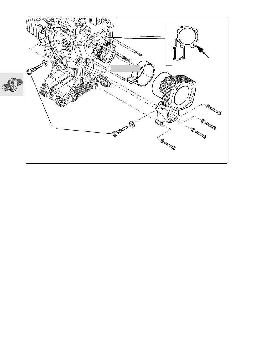
Installing cylinder

•

Apply 3-Bond 1209 to the cylinder base sealing 
face (arrow), which must be clean and free from 
grease.

•

Oil the cylinder wall.

•

Compress the piston rings with a clamping strap, 
BMW No. 11 2 900.

•

Install the cylinder and at the same time pass the 
timing chain and the tensioning and guide rail 
through the timing case cavity.

•

Tighten cylinder down firmly.

•

Fit new seal to pivot pin for chain guide rail (1).

•

Install chain sprocket.

X 

Tightening torque/tightening order:

1. M 8 screw ................................................ 20 Nm
2. M 6 screw .................................................. 9 Nm
3. Pivot screw for chain guide rail.................... 18 Nm

11 2 900

RS110420

1

u

11.55

Installing cylinder head

•

Install cylinder head gasket.

•

Fit cylinder head/insert correctly positioned cam-
shaft chain sprocket (1) and timing chain into 
chain cavity.

•

Install valve gear support (2).

•

Tighten cylinder head down.

e

 Caution:

Install collar (arrow) of cylinder head nut towards cyl-
inder head.

X 

Tightening torque/tightening order:

1. Tighten cylinder head nuts (oiled) crosswise
1.1 Tighten all nuts....................................... 20 Nm
1.2 Tighten all nuts to correct angle .................. 90°
1.3 Tighten all nuts to correct angle .................. 90°
2. M 10 bolt................................................ 40 Nm
3. M 6 screw ................................................ 9 Nm

X 

Tightening torque: 

Take up slack after 1000 km (app. 600 miles) 
Tighten cylinder head nuts in a crosswise pattern
1. Unfasten one nut
2. Tighten one nut to initial value ................. 20 Nm
3. Tighten nut to wrench angle ......................  180°
4. Unfasten/retighten M10 screw ................ 40 Nm

•

Fit camshaft chain sprocket in accordance with 
adjustment specification.

•

Lock clutch housing with special tool 
BMW No. 11 5 640.

•

Tighten camshaft chain sprocket.

X 

Tightening torque:

Camshaft sprocket retaining screw .............. 65 Nm

•

Insert the left-side camshaft sprocket with pin 
into the camshaft and set the left cylinder to TDC 
on the ignition stroke.

•

Fit camshaft chain sprocket in accordance with 
adjustment specification.

•

Tighten camshaft chain sprocket.

•

Install chain tensioner.

•

Check that marks on camshaft sprockets are in 
accordance with adjustment specification. 

X 

Tightening torque:

Chain tensioner ............................................ 32 Nm

RS110930

M6 x 30

M6 x 30

M6 x 30

M6 x 60

2

1

11.56

Adjusting valve clearances

•

Set piston to TDC on the ignition stroke.

•

Measure valve clearance with feeler gauge.

•

Correct valve clearance with adjusting screw and 
lock into position.

Valve clearances with engine cold
(max. 35 °C/95 °F): 
Inlet ........................................... 0.15 mm (0.006 in)
Exhaust ..................................... 0.30 mm (0.012 in)

X 

Tightening torque:

Locknut .......................................................... 8 Nm

•

Check valve clearance again; it must be possible 
to insert the feeler gauge between valve stem 
and rocker with only slight resistance to move-
ment.

RS110980

11.57

Installing right cylinder head

Adjustment specification

e

 Caution:

When assembling, always start with the right cylin-
der.

Right cylinder = at TDC on ignition stroke:
marks (arrows) on chainwheel/auxiliary shaft and 
chain sprocket/crankshaft are aligned.

•

Locate ignition-stroke TDC with insert pin,
BMW No. 11 2 650, at hole in clutch housing 
and engine block.

L

 Note:

With the engine installed, adjust TDC with dial gauge 
holder,  BMW No. 00 2 650, and dial gauge, 
BMW No. 00 2 510.

Right cylinder = at TDC on ignition stroke:
Locating pin (arrow) on right camshaft sprocket 
points downwards.
Mark (R or arrow) and tip of tooth on right camshaft 
sprocket is precisely aligned with mark X on timing 
gear carrier.

•

Check setting again with timing chain tensioner 
installed.

RS110961

RS110150

X

11.58

Installing left cylinder head

Adjustment specification

e

 Caution:

When installing, always begin with the right cylin-
der.

Left cylinder = TDC on ignition stroke: marks (ar-
rows) on chain sprocket/auxiliary shaft and chain-
wheel/crankshaft face down

•

Locate ignition-stroke TDC with insert pin,
BMW  No. 11 2 650, at hole in clutch housing 
and engine block.

L

 Note:

With engine installed, adjust to TDC with dial gauge 
holder, BMW No. 00 2 650, and dial gauge, 
BMW No. 00 2 510.

Left cylinder = at TDC on ignition stroke:
Locating pin (arrow) on left camshaft sprocket points 
upwards.
Mark (R or arrow) and tip of tooth at left camshaft 
sprocket is aligned precisely with mark X on timing 
gear carrier.

•

Check setting again with timing chain tensioner 
installed.

RS110963

RS110511

X

11.59

•

Install the end cover with an O-ring which is in 
good condition.

X 

Tightening torque:

M 6 screw ...................................................... 9 Nm

•

If necessary, reduce end play to a minimum by 
repositioning the bearings.

Rocker end float:
min. ........................................... 0.05 mm (0.002 in)
max. .......................................... 0.40 mm (0.016 in)

•

Install cylinder head cover.

e

 Caution:

Ensure that gaskets are properly seated. Gaskets 
and sealing face must be free from oil and grease.

X 

Tightening torque:

Cover screw................................................... 8 Nm

•

Tighten air intake stub pipe.

X 

Tightening torque:

M 6 screw ...................................................... 9 Nm

RS110050

RS110100

RS110940

RS110440

11.60

Installing alternator mount cover

•

Place sliding sleeve, BMW No. 11 5 680, on 
crankshaft.

•

Apply 3-Bond 1209 to the sealing face (arrow), 
which must be clean and free from grease. 

•

Install alternator mount cover.

X 

Tightening torque:

M 8 screw .................................................... 20 Nm
M 6 screw ...................................................... 9 Nm

Installing magnetic gate/belt pulley

•

Install Hall-effect trigger plate (1).

•

Lock clutch housing with special tool 
BMW No. 11 5 640.

•

Secure rotor (2) of Hall-effect gate to the Poly-V 
belt pulley (3) with, for example, Loctite instant 
adhesive.

•

Install the Poly-V belt pulley.

e

 Caution:

Install retainer for Hall-effect gate rotor (4) at groove 
in crankshaft (5).

X 

Tightening torque:

Retaining screw for belt pulley...................... 50 Nm

•

Install rotary breather pipe (6) with new sealing 
rings.

X 

Tightening torque:

Vent line to alternator mount cover
M 8 screw .................................................... 20 Nm
Banjo screw ................................................. 25 Nm

11 5 680

RS110450

11 5 640

6

3

2

1

4

5

u

11.61

Timing the ignition

•

Using TDC locating pin, BMW No. 11 2 650, lock 
the clutch housing.

•

Connect BMW MoDiTeC with adapter cable to 
Hall-effect gate plate.

•

Adjust in accordance with tester guidance.

•

Remove the TDC locating pin.

11 2 650

RS110461


Content   ..  9  10  11  12   ..