BMW AG Motorcycle (R 850 C, R 1200 C). Manual - part 6


  Index      Manuals     BMW AG Motorcycle (R 850 C, R 1200 C). Repair Manual


Search            


Content   ..  4  5  6  7   ..


BMW AG Motorcycle (R 850 C, R 1200 C). Manual - part 6


11.13

Coolant circuit
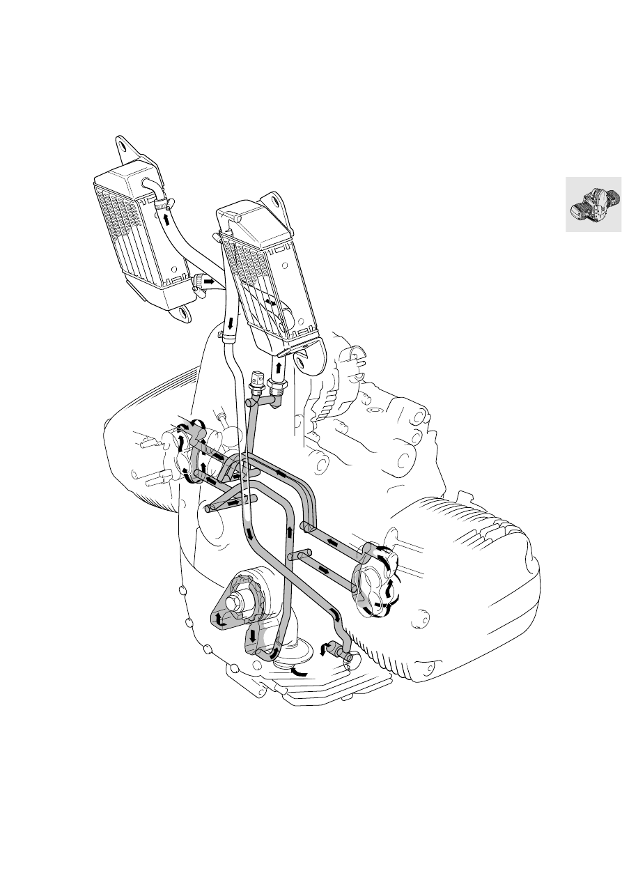
11.15

Removing engine

L

 Note:

Auxiliary shaft, timing chains, chain tensioner/guide 
rails and crankshaft can only be dismantled after the 
engine has been removed. All other components 
can be dismantled while the engine is still installed.

•

Drain engine oil.

•

Drain the brake system completely.

•

Drain the clutch operating system completely.

•

Attach auxiliary stand, BMW No. 00 1 550, to the 
motorcycle.

•

Attach stand, BMW No. 00 1 520, to motorcycle.

•

Remove seat.

•

Remove side trim.

•

Remove fuel tank.

•

Remove the battery.

e

 Caution:

Disconnect negative terminal first, then positive ter-
minal.

•

Remove rear wheel.

•

Detach the rear brake caliper.

•

Detach the ABS sensor.

•

Detach the speedometer sensor.

•

Remove exhaust manifold.

•

Remove silencer (muffler).

•

Separate oxygen sensor plug.

•

Remove line protection from swinging arm.

•

Tie the swinging arm up to the rear frame with a 
strap.

•

Remove suspension strut.

L

 Note:

Press the upper suspension strut to the rear.

•

Remove rear wheel drive unit.

•

Detach brake hose holder at rear frame.

•

Press off the left swinging arm bearing cap.

e

 Caution:

When installing, make sure the O-ring is in good 
condition.
Install with the drain hole pointing down.

•

Loosen the left swinging arm bearing.

•

Loosen the screws at the right swinging arm 
bearing.

•

Use pull rod, BMW No. 00 8 581, and impact 
weight, BMW No. 00 8 582, to pull out the 
swinging arm bearing.

•

Remove the left swinging arm bearing.

C360011

00 1 550

C110010

00 1 520

C330030

C330040

00 8 582

00 8 581

11.16

•

Remove rear swinging fork.

•

Press off drive shaft.

•

Remove the air intake stub pipe.

•

Remove brake fluid reservoir from holder.

•

Remove the holder.

•

Take off the right plug retaining plate.

•

Pull the air temperature plug off the air cleaner 
cover.

•

Detach the gear lever at the pivot.

•

Remove the gear lever.

•

Separate the plug for the throttle angle potenti-
ometer and the throttle positioner at the left plug 
retaining plate.

•

Disconnect both fuse boxes at the plug retaining 
plate.

•

Separate the side (prop) stand safety switch 
plug.

•

Separate the neutral indicator plug.

•

Detach the left plug retaining plate.

•

Remove the injector nozzles.

•

Pull the plug off the injector line.

•

Separate the  plug for the rear brake light switch 
and detach the wire.

•

Detach the vent hose at the air cleaner housing.

•

Disconnect the throttle cable at the twistgrip. 

•

Remove rear section of frame.

•

Remove the auxiliary stand.

•

Remove the footrest holder.

•

Remove the starter motor cover.

•

Detach cable from starter motor.

•

Remove the starter motor.

•

Separate the clutch line where it passes through 
the frame.

•

Remove the clutch slave cylinder with line.

•

Pull out the thrust rod.

•

Detach the gearbox.

•

When removing the gearbox, pull it out on guide 
pins, BMW No. 23 1 820.

•

Remove the Motronic control unit.

•

Disconnect the wires in the central electrical 
equipment box.

–

Instruments

–

Right combined switch

–

Left combined switch

–

Front brake light switch

–

Clutch switch

–

Front ABS sensor

•

Undo the cable straps at the wiring.

•

Detach the central electrical equipment box.

•

Remove the brake lines from the pressure mod-
ulator to the front junction box.

•

Detach the lines at the pressure modulator.

•

Remove the ABS unit.

e

 Caution:

Comply exactly with the instructions in the Repair 
Manual.
aGroup 34

•

Remove battery carrier.

•

Remove the horn.

•

Remove the ignition coil.

•

Pull off the plug cap with special puller,
BMW No. 12 3 520, and remove the ignition lead.

•

Open the headlight housing.

•

Detach the headlight cable.

•

Detach the flashing turn indicator wires.

•

Detach the oil pressure switch wire.

•

Detach the alternator cables.

C330050

RS230010

23 1 820

C340011

11.17

•

Detach the central earth (ground) wire at the en-
gine block.

•

Remove the left air intake pipe at the cylinder 
head.

•

Heat the ball joint mount at the leading link to 
max. 120 °C (248 °F) and detach it.

e

 Caution:

Do not scratch the surface of the leading link.

•

Detach the line for the front brake caliper at the 
junction block/frame.

•

Remove the caps from the threaded connections 
on the fixed tubes.

•

Separate the fixed tube from the fork bridge at 
the threaded connections.

•

Remove the telescopic fork.

•

Remove the cover plate over the upper suspen-
sion strut mount on the frame.

•

Remove suspension strut.

•

Remove the leading link caps.

•

Remove the left screw cap.

•

Remove the circlip at the right and the safety 
cap.

•

Take out the screw at the right and pull the shaft 
out to the left.

•

Remove the leading link.

•

Detach the hose for the oil cooler at the engine.

•

Remove frame.

•

Install by following the above work instructions in 
the reverse order.

11.18

Dismantling engine

•

Attach engine mount, BMW No. 11 0 630, to the 
engine block.

•

Transfer engine to assembly frame.

•

Drain engine oil.

•

Remove the oil filter, using oil filter wrench, 
BMW No. 11 4 650.

00 0 630

RS110010

11 4 650

RS110950

11.19

Removing cylinder head cover

•

Unscrew and remove spark plug with the spark 
plug wrench, BMW No. 12 3 510.

•

Remove cylinder head cover.

e

 Caution:

Trap escaping oil.

12 3 510

RS110020

11.20

Locking the engine in the TDC 
position

•

Remove front cover.

•

Turn the belt pulley to move the piston to TDC on 
the ignition stroke.

Top dead centre on ignition stroke:
1. TDC mark is visible, and
2. The inlet and exhaust valves in the cylinder in 

question are closed.

•

Prevent the clutch housing from moving with 
locking device, BMW No. 11 5 640.

L

  Note:

The engine can be correctly positioned  at TDC with 
locating pin, BMW No. 11 2 650, through the hole in 
the clutch housing and the engine block.

RS110030

11 5 640

TDC

RS110461

11 2 650

TDC

11.21

Removing and installing chain
tensioner

e

 Caution:

Do not accidentally confuse the chain tensioner pis-
tons. When installing, fit a new gasket.

Assembly specification for timing chain ten-
sioner:
Removal:

•

Remove timing chain tensioner, then remove 
camshaft sprocket from camshaft.

Installing:

•

First install camshaft sprocket, then timing chain 
tensioner.

e

 Caution:

Failure to observe this sequence can cause the 
chain tensioner piston to fall into the left side of the 
timing chain cavity.

X 

Tightening torque:

Chain tensioner ............................................ 32 Nm

RS110060


Content   ..  4  5  6  7   ..