BMW AG Motorcycle (K1100LT, K1100RS). Manual - part 11
 

  Index      Manuals     BMW AG Motorcycle (K1100LT, K1100RS). Repair Manual


Search            


Content   ..  9  10  11  12   ..


BMW AG Motorcycle (K1100LT, K1100RS). Manual - part 11


12.5

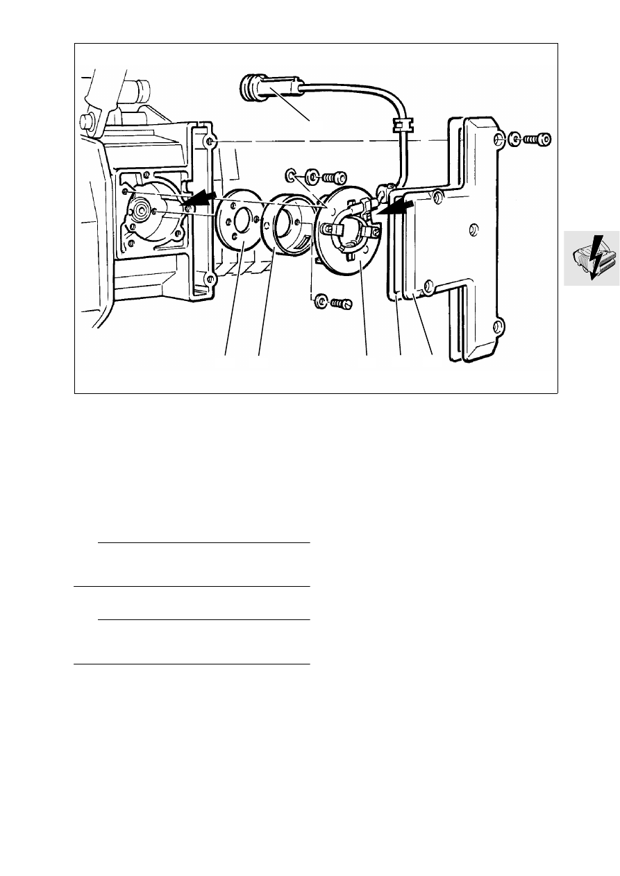
Removing and installing Hall gener-
ator

•

Disconnect ground lead of battery and insulate.

•

Remove radiator cowling.

•

Remove fuel tank.

•

Disconnect Hall generator (1) plug connection.

•

Remove cover (2) together with gasket (3).

•

Remove base plate (4).

•

Remove rotor (5) and setting plate (6).

L

 Note:

Mark installation position of setting plate on engine 
case, or remove in TDC position.

•

Install in the reverse order of removal.

L

 Note:

The recess on the engine case and on the base 
plate must be aligned flush.

X 

Tightening torques:

Base plate ................................................... 3.5 Nm
Cover ............................................................. 9 Nm

LT120010

6

1

5

4

3

2

12.6

Adjusting ignition timing

•

Remove radiator cowling.

•

Remove bottom left fairing.

•

Remove fuel tank.

•

Disconnect plug connection on Hall generator 
lead under the fuel tank.

•

Connect adapter lead (2), BMW  No. 12 3 651, to 
Hall generator lead.

•

Connect ignition setting device (3), 
BMW No. 12 3 650,to adapter line.

•

Disconnect spark plug connector with flat-nose 
pliers.

•

Unscrew spark plugs with spark plug box span-
ner, BMW No. 12 3 500.

•

Screw dial gauge with extension (1), 
BMW No. 00 2 580, into cylinder No. 1.

•

Set piston to TDC.

•

Set scale ring of dial gauge to 0.

•

Turn engine back in clockwise direction until pis-
ton setting ignition point is reached.

Ignition point:
6 ° before TDC = 0.24 mm (0.00945 in) before TDC

LT120020

2

1

3

12 3 650

12 3 651

12 3 650

00 2 580

LT120030

12.7

•

Loosen base plate (1) and turn to the left or right 
until diode (2) on ignition setting device goes out.

L

 Note:

Ignition timing adjustment
Turn to left

Retard ignition

Turn to right

Advance ignition

•

Firmly tighten base plate.

•

Check ignition timing:
Crank engine in normal direction. The diode on 
the ignition setting device must go out at piston 
position 0.24 (0.00945 in) mm before TDC.

X 

Tightening torques:

Base plate ................................................... 3.5 Nm
Cover ............................................................. 9 Nm
Spark plug.................................................... 20 Nm

12 3 650

LT120040

1

2

12.8

Removing and installing ignition 
coils

•

Disconnect earth (ground) lead of battery and in-
sulate.

•

Remove top (1) and bottom (2) ignition coil cover.

•

Disconnect plug connector (3) at the ignition 
coils.

•

Disconnect plug connector (4) for terminal “1” 
and “15”.

•

Release earth (ground) connection (5) on starter.

•

Release top and bottom mounting at intermedi-
ate flange (6).

•

Install in the reverse order of removal.

L

 Note:

Note assignment of ignition leads to ignition coil. Ig-
nition coils are also marked.

X 

Tightening torque:

Ignition coils to intermediate flange ................ 5 Nm

LT120050

1

4

6

2

3

5

12.9

Removing and installing ignition 
output stage

•

Remove left battery bracket.

•

Disconnect earth (ground) lead of battery.

•

Remove ignition coils.

•

Remove ignition output stage (1).

•

Press retaining clip (2) and detach ignition output 
stage.

•

Install in the reverse order of removal.

L

 Note:

Before installing the ignition output stage, coat the 
rear with heat conducting paste Curil K 2.

LT120060

3

2

1

12.10

Removing and installing alternator

•

Remove right battery panel.

•

Remove Motronic control unit.

•

[ABS I] Remove ABS control unit.

•

Remove battery.

•

Remove cover (1).

•

Disconnect plug (2).

•

Remove alternator.

•

Install in the reverse order of removal.

X 

Tightening torque:

Alternator ...................................................... 22 Nm

LT120070

1

2

12.11

Disassembling and assembling 
alternator

Alternator


[only LT up to 1992 model year]

•

Remove damper elements (1)

•

Remove coupling housing (2) with holding tool 
(3), BMW No. 12 4 600.

•

Pull off fan wheel (4).

•

Remove key (5).

•

Release retaining screw (6) for bearing end plate.

•

Clamp alternator in vice with jaw guards.

•

Remove bearing end plate (7) with three-point 
puller, BMW No. 33 1 830.

X 

Tightening torque:

Coupling housing...........................................50 Nm

LT120080

5

7

6

4

2

1

12 4 600

LT120090

2

3

12.12

•

Remove regulator (8) with carbon brushes.

•

Carefully lift out armature (9) together with bear-
ing (10).

•

Remove bearing (10) from armature shaft.

•

Unsolder stator (11) on diode plate (12); mark the 
wires.

•

Remove diode plate.

•

Remove O-ring (14).

•

Install in the reverse order of removal.

L

 Note:

During assembly, insulate the solder points on the 
diode plate with silicone. Coat bearing seat in hous-
ing with Molykote paste.

Checking exciter winding

•

Using the test probes of the BMW diagnosis test-
er, 

BMW No. 61 1 510

, measure the resistance 

across the slip rings.

Nominal resistance.......................................7 ± 1


Ω

LT120100

9

11

10

14

13

8

12

61 1 510

LT120110


Content   ..  9  10  11  12   ..