BMW AG Motorcycle (K1100LT, K1100RS). Manual - part 2
00.11
Key to maintenance intervals
–
Inspection at 1000 km (600 miles)I
–
BMW Service at 10,000 km (6000 miles))II
–
BMW Inspection at 20,000 km (12,000 miles)III
–
BMW Annual Service
IV
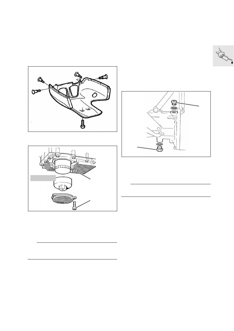
Changing engine oil
Inspections I, II, III, IV
•
[RS] Remove lower section of fairing.
•
Change oil at operating temperature.
•
Oil drain plug (1).
•
Remove oil filter cover retainer (2).
•
Unscrew oil filter with special wrench
BMW No. 11 4 650.
L
Note:
Coat sealing ring on new oil filter element with oil.
Screw in oil filter handtight, take note of hint at filter.
•
Replace O-ring in cover, if necessary.
X
Tightening torques:
Oil drain plug................................................ 18 Nm
Cover to oil sump ........................................... 6 Nm
Quantities:
Oil content ................................ 3.50 l (6.16 Imp.pt)
Oil content with filter change ....... 3.75 l (6.6 Imp.pt)
See service data for oil grades ................ Seite 00.3
Changing oil in transmission
(gearbox)
Inspections I, III, IV
•
Drain off oil with engine at operating tempera-
ture.
•
Oil drain plug (1)
•
Oil filler plug (2)
L
Note:
Renew sealing rings.
X
Tightening torques:
Oil drain plug................................................ 20 Nm
Oil filler plug ................................................. 20 Nm
Quantities:
Oil filling capacity .................... 0.85 l (1.496 Imp.pt)
See service data for oil grades ................Page 00.3
LT000010
LT000020
1
2
11 4 650
LT000030
2
1