Motorcycle BMW R1150RT. Manual - part 66
 

  Index      motorcycles     Motorcycle BMW R1150RT - service repair manual 2001 year


Search            


Content   ..  64  65  66  67   ..


Motorcycle BMW R1150RT. Manual - part 66


34.9

34 11  

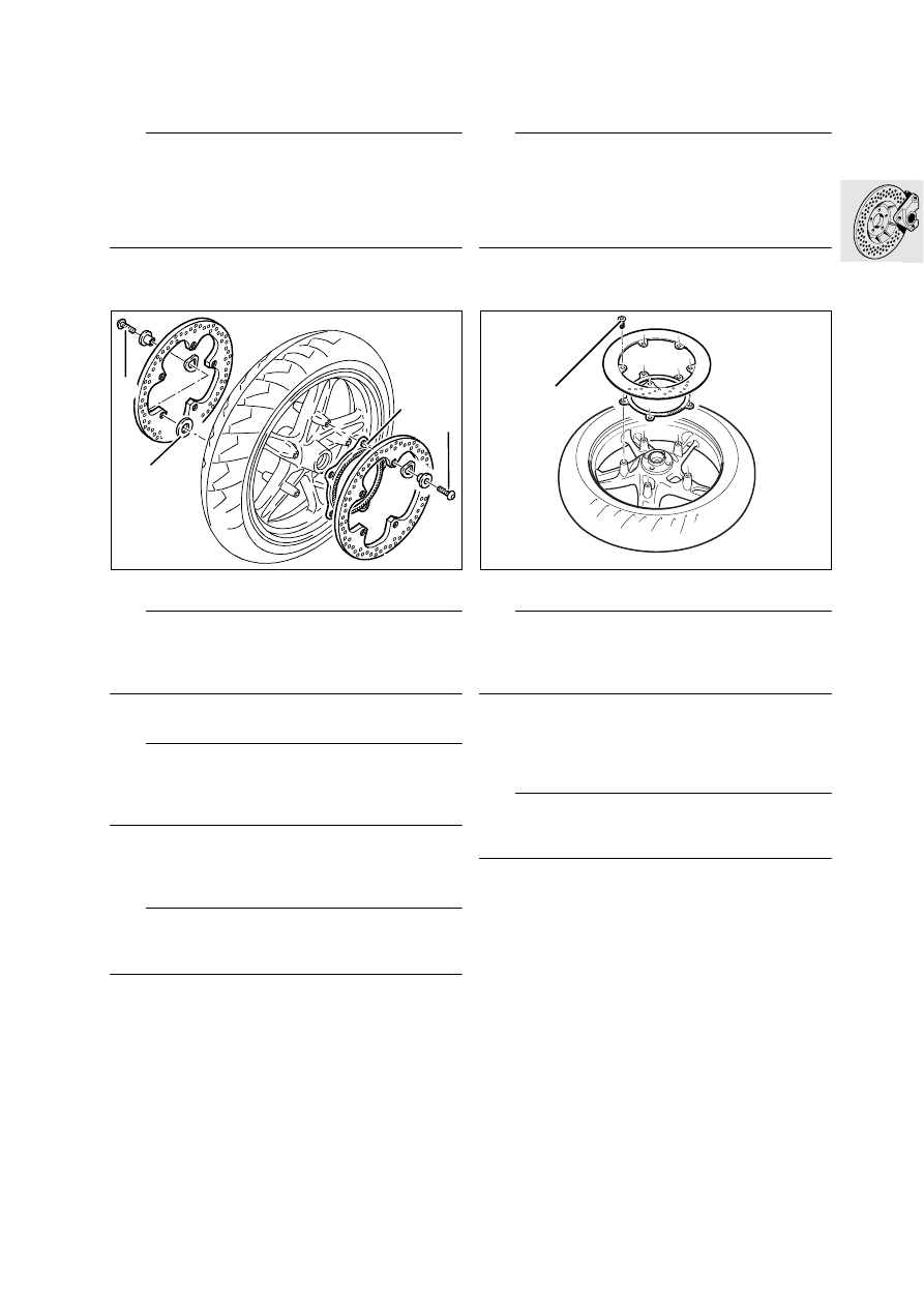
Removing and installing front 

brake discs

d

 Warning:

When removing and installing the brake calipers, 
force back the pistons carefully to ensure that the 
wheel-circuit reservoir does not overflow.
If fluid escapes, proceed in accordance with “In-
structions for filling reservoir” (

a

34.26).

•

Remove the brake calipers.

•

Remove front wheel.

L

 Note:

Retaining screws (1) are secured with thread-lock-
ing compound and should be heated if necessary 
before removal.

•

Remove brake discs.

e

 Attention:

Note thrust washers between right brake disc and 
front wheel, and note ABS sensor ring between left 
brake disc and front wheel.

•

Install ABS sensor ring (2) on left and thrust 
washers (3) on right beneath brake disc. 

•

Degrease brake discs before installing.

e

 Attention:

Install brake discs right way round (inscriptions on 
brake discs facing toward the outside).

X 

Tightening torque:

Brake disc to front wheel
(clean thread + Loctite 2701).......................  21 Nm

34 21  

Removing and installing rear 

brake disc 

d

 Warning:

When removing and installing the brake caliper, 
force back the pistons carefully to ensure that the 
wheel-circuit reservoir does not overflow.
If fluid escapes, proceed in accordance with “In-
structions for filling reservoir” (

a

34.29).

•

Remove the brake caliper.

•

Remove rear wheel.

L

 Note:

Retaining screws (1) are secured with thread-lock-
ing compound and should be heated if necessary 
before removal.

•

Remove brake disc.

•

Installation is the reverse of the removal proce-
dure.

•

Degrease the brake disc before installing.

e

 Attention:

Make sure the spacer is fitted when the rear wheel 
is installed.

X 

Tightening torque:

Brake disc to rear wheel drive 
(clean thread + Loctite 2701).......................  21 Nm

R28340150

1

1

2

3

R28340130

1

34.10


Removing and installing Integral 

ABS sensor

34 52 044 

Removing and installing front 

Integral ABS sensor

•

Remove the cable ties securing the sensor ca-
ble.

•

Disconnect plug (1) of sensor cable.

•

Guide the sensor cable down until clear.

•

Remove sensor (2).

•

Installation is the reverse of the removal proce-
dure.

e

 Attention:

Route the sensor cable correctly.
Ensure that clips (3) are correctly seated.

X 

Tightening torque:

Sensor  ........................................ hand-tight, 4 Nm

R22340060

1

3

2

3

34.11

34 52 111  

Removing and installing rear 

Integral ABS sensor

•

Remove front and rear seats.

•

Remove right case, if necessary.

•

Remove small right side fairing panel.

•

Remove the cable ties securing the sensor ca-
ble.

•

Disconnect plug (1) of sensor cable.

•

Before removing/installing, clean the sensor 
bore.

•

Remove sensor (2).

•

Installation is the reverse of the removal proce-
dure.

•

Coat O-rings with oil before installing.

e

 Attention:

Route the sensor cable correctly.

X 

Tightening torque:

Sensor  ........................................ hand-tight, 4 Nm

1

2

R22340070

34.12

35 21  

Removing and installing foot-

brake lever

•

Release and remove stud (1).

•

Remove screw (2) of footbrake lever with nut (3). 

•

Remove footbrake lever with torsion spring (4).

•

Installation is the reverse of the removal proce-
dure.

•

Lubricate pivot bushing with Shell Retinax A.

e

 Attention:

Check and, if necessary, adjust the blow-by clear-
ance of the piston rod and the setting of the brake-
light switch (

a

34.13).

X 

Tightening torque:

Footbrake lever to footrest plate
(clean thread + Loctite 2701)........................ 21 Nm

34 31  

Removing and installing rear 

brake master cylinder

•

Remove right side panel.

e

 Attention:

Do not allow brake fluid to come into contact with 
painted parts of the motorcycle as brake fluid de-
stroys paint.

•

Integral ABS Drain rear control circuit
(

a

34.19).

•

Disconnect brake line (5) and hose (6).

•

Release and remove stud (1).

•

Remove brake master cylinder.

•

Installation is the reverse of the removal proce-
dure.

•

Tighten non-reusable hose clip (7) with pliers, 
BMW No. 13 1 500.

•

Integral ABS Fill and bleed rear control circuit 
(

a

34.22).

e

 Attention:

Bleed the brake system carefully.
Check and, if necessary, adjust the blow-by clear-
ance of the piston rod and the setting of the brake-
light switch (

a

34.13).

X 

Tightening torque:

Master brake cylinder to footrest.................... 9 Nm

R22460140

1

2

3

4

5

6

7


Content   ..  64  65  66  67   ..