Motorcycle BMW R1150RT. Manual - part 24
 

  Index      motorcycles     Motorcycle BMW R1150RT - service repair manual 2001 year


Search            


Content   ..  22  23  24  25   ..


Motorcycle BMW R1150RT. Manual - part 24


11.31

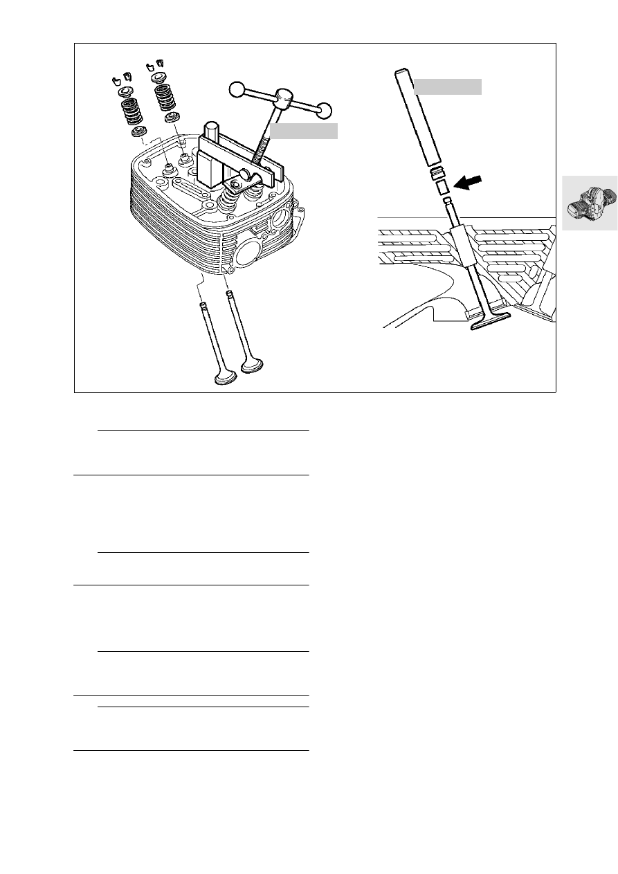
11 34 Installing valve and valve stem seal

L

 Note:

The valve stem seal must be replaced whenever a 
valve is removed.

•

Oil the stem before installing the valve.

•

Shrink a short length of tube (arrow) on to the end 
of the valve stem.

•

Install the valve stem seal with a 
5 mm (0.1969 in) dia. drift, BMW No. 11 5 602.

e

 Attention:

Remove the shrink-fit tube.

•

Install lower spring retainer, valve spring and up-
per spring retainer. 

•

Compress the valve springs with the valve spring 
compressor, BMW No. 11 5 690. 

L

 Note:

Apply grease to valve collets (to facilitate installation) 
and install.

e

 Attention:

Make sure that valve collets are correctly seated in 
the valve stem grooves.

•

Relieve tension on valve springs.

•

Check valves for leakage (blow-by).

11 5 690

RS110160

11 5 602

11.32

11 11 120 

Removing cylinder

•

Remove guide rail bearing screws (1).

e

 Attention:

When removing the cylinder, use care to prevent the 
piston from knocking against the engine casing.

•

Remove cylinder retaining screws, and remove 
cylinder.

11 25 000 

Removing and disassembling 

piston assembly

e

 Attention:

Do not mix up pistons, piston pins and piston rings.

•

Remove both retaining rings from piston pin.

•

Press out piston pin by hand.

•

Remove piston.

•

Carefully remove piston rings with piston ring pli-
ers.

•

Remove combustion residues from piston crown 
and clean piston.

RS110170

1

11.33

11 25 

Checking pistons and cylinders

Reference temperature for measurements: 

........................................................... 20 

ƒC (68 °F)

Measure cylinder bore with internal probe at 
20 mm (0.7874 in) and 100 mm (3.9370 in) from the 
top in direction of piston pin, and again at a right an-
gle to the first measurement (

a

11.10).

Measuring plane A:..................... 6 mm (0.2362 in)
Piston sizes (

a

11.11).

•

Install piston rings in cylinder.

•

Measure end gap using feeler gauge (

a

11.11).

11 25 

Assembling pistons

L

 Note:

Make sure that the gap of the coiled spring is offset 
approximately 180° from the gap of the oil control 
ring.
Install with “TOP” uppermost.

•

Carefully fit piston rings to piston in the following 
sequence, using piston ring pliers: 
3rd groove - coiled-spring ring
2nd groove - micro-chamfer ring 
1st groove - asymmetric piston ring, oval section
(

a

11.11).

RS110180

100

20

RS110970

A

RS110200

R21110050

1.

2.

3.

11.34

11 24 030 

Removing and installing con-

rods

•

Turn crankshaft to TDC position.

•

Install locking device, BMW No. 11 5 640, to 
lock clutch housing.

e

 Attention:

Make sure that conrods and bearing shells are rein-
stalled in their original positions.
Use a felt-tipped pen or similar to mark the installed 
positions on the conrods.

•

Remove connecting rods.

L

 Note:

Connecting rods can also be removed and installed 
with the crankshaft removed.

e


Attention:

Oil the bearings. Never re-use the big end bolts.

•

Install conrods.

•

Oil the big end bolts, screw them in by hand and 
tighten with commercially available angle-of-ro-
tation indicator or tightening angle indicator, 
BMW No. 11 2 500
.

L

 Note:

When using tightening angle indicator, 
BMW No. 11 2 500, make sure the extensions are 
of the same length. 
Use a 3/8" square-drive socket wrench.

X 

Tightening torque:

Big end bolts, oiled
Initial torque ................................................. 20 Nm
Tightening angle............................................... 80 °

11 5 640

R21110040

TD

11 2 500


Content   ..  22  23  24  25   ..