Kawasaki Ninja ZX-12R Motorcycle. Service Manual (2002-2005 year) - page 15
 

  Index      Manuals     Kawasaki Ninja ZX-12R Motorcycle. Service Manual (2002-2005 year)


Search            copyright infringement  


Content      ..     13      14      15      16     ..


Kawasaki Ninja ZX-12R Motorcycle. Service Manual (2002-2005 year) - page 15


14-2 STEERING

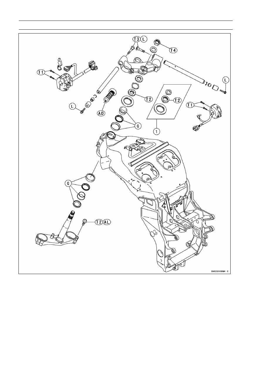
Exploded View

1. ZX1200-B1/B2

T1: 3.5 N·m (0.36 kgf·m, 31 in·lb)
T2: 20 N·m (2.0 kgf·m, 15 ft·lb)
T3: 34 N·m (3.5 kgf·m, 25 ft·lb)
T4: 54 N·m (5.5 kgf·m, 40 ft·lb) (ZX1200-B1/B2)

78 N·m (8.0 kgf·m, 57 ft·lb) (ZX1200-B3

∼

)

AD: Apply adhesive.

AL: Tighten the two clamp bolts alternately two times to ensure even tightening torque.

G: Apply grease.

L: Apply a non-permanent locking agent.

STEERING 14-3

Specifications

Special Tools - Head Pipe Outer Race Press Shaft: 57001-1075

Steering Stem Nut Wrench: 57001-1100
Head Pipe Outer Race Remover ID > 37 mm: 57001-1107
Jack: 57001-1238
Steering Stem Bearing Driver, 42.5: 57001-1344
Steering Stem Bearing Driver Adapter, 41.5: 57001-1345
Head Pipe Outer Race Driver, 55: 57001-1446
Head Pipe Outer Race Driver, 47: 57001-1447

14-4 STEERING

Steering

Steering Inspection

•

Refer to the Steering Inspection in the Periodic Mainte-
nance chapter.

Steering Adjustment

•

Refer to the Steering Inspection in the Periodic Mainte-
nance chapter.

STEERING 14-5

Steering Stem

Stem, Stem Bearing Removal

•

Remove:

Brake Hose Joint Cover Screws [A]
Front Wheel (see Wheels/Tires chapter)
Front Fork (see Suspension chapter)
Steering Stem Head Nut and Washer
Steering Stem Head with Handlebars

•

Remove the brake hose joint bolt [A].

ZX1200-B1/B2

•

Take off the lock washer [A] to remove the steering stem
nut [B] and pull the steering stem [C] with the bearing and
oil seal downward.

Special Tool - Steering Stem Nut Wrench: 57001-1100

•

Remove the oil seal, bearing inner race and ball bearing
assy from the upper head pipe.

ZX1200-B3

∼

•

Straighten the claw washer tabs [A].

•

Remove the steering stem locknut [B].

Special Tool - Steering Stem Nut Wrench: 57001-1100

•

Remove the claw washer [A].

14-6 STEERING

Steering Stem

•

Pushing up the stem base, and remove the steering stem
nut [A] with oil seal.

Special Tool - Steering Stem Nut Wrench [B]: 57001-1100

•

Remove:

Steering Stem [C]
Upper Ball Bearing Inner Race

•

Drive out the bearing outer races [B] from the head pipe.

Special Tool - Head Pipe Outer Race Remover ID > 37 mm:

57001-1107 [A]

NOTE

○

If either steering stem bearing is damaged, it is recom-
mended that both the upper and lower bearings (includ-
ing outer races) should be replaced with new ones.

•

Remove the lower inner race [A] (with its grease seal [B])
which is pressed onto the steering stem with a suitable
commercially available bearing puller or chisel [C].

Stem, Stem Bearing Installation

•

Replace the outer races, inner races and ball bearings
with new ones.

•

Apply grease to the outer races, and drive them into the
head pipe at the same time.

Special Tools - Head Pipe Outer Race Press Shaft: 57001

-1075 [A]

Head Pipe Outer Race Driver,

55: 57001

-1446

Head Pipe Outer Race Driver,

47: 57001

-1447 [B]

STEERING 14-7

Steering Stem

•

Install the oil seal [A] on the steering stem, and drive the
lower ball bearing inner race [B] applied the grease on to
the stem.

Special Tools - Steering Stem Bearing Driver, 42.5: 57001

-1344 [C]

Steering Stem Bearing Driver Adapter,

41.5: 57001-1345 [D]

•

Install the lower ball bearing [A] onto the stem.

•

Apply grease to the lower and upper ball bearings [B] and
outer races.

•

Install the stem [A] through the head pipe and install the
ball bearing [B] and inner race [C] on it.

•

Install the oil seal [D] and steering stem nut [E].

•

Settle the inner races in place as follows:

○

Tighten the steering stem nut with 20 N·m (2.0 kgf·m, 15
ft·lb) of torque first, and loosen it a fraction of a turn until
it turns lightly. Afterward tighten it again with specified
torque using the stem nut wrench [A].

○

Check that there is no play and the steering stem turns
smoothly without rattles. If not, the bearings on the inner
races may be damaged.

Special Tool - Steering Stem Nut Wrench: 57001-1100

Torque - Steering Stem Nut: 20 N·m (2.0 kgf·m, 15 ft·lb)

14-8 STEERING

Steering Stem

ZX1200-B1/B2

•

Install the lock washer.

•

Install the stem head.

•

Install the washer, and tighten the stem head nut with
specified torque.

•

Install the front fork (see Suspension chapter).

NOTE

○

Tighten the fork upper clamp bolts first, next the stem
head nut, last the fork lower clamp bolts.

○

Tighten the two clamp bolts alternately two times to en-
sure even tightening torque.

Torque - Steering Stem Head Nut: 54 N·m (5.5 kgf·m, 40

ft·lb)

Front Fork Clamp Bolts (Upper):

20 N·m (2.0 kgf·m, 15 ft·lb)

Front Fork Clamp Bolts (Lower):

20 N·m (2.0 kgf·m, 15 ft·lb)

WARNING

Do not impede the handlebar turning by routing the
cables, harnesses and hoses improperly (see Gen-
eral Information chapter).

•

Install the removed parts (see appropriate chapters).

ZX1200-B3

∼

•

Install the claw washer [A] so that its bent side [B] faces
upward, and engage the bent claws with the grooves of
stem locknut [C].

•

Hand tighten the stem locknut until it touches the claw
washer.

•

Tighten the stem locknut clockwise until the claws are
aligned with the grooves of stem nut [D], and bend the
2 claws downward [E].

•

Install the stem head.

•

Install the washer, and tighten the stem head nut with
specified torque.

•

Install the front fork (see Suspension chapter).

STEERING 14-9

Steering Stem

NOTE

○

Tighten the fork upper clamp bolts first, next the stem
head nut, last the fork lower clamp bolts.

○

Tighten the two clamp bolts alternately two times to en-
sure even tightening torque.

Torque - Steering Stem Head Nut: 78 N·m (8.0 kgf·m, 57

ft·lb)

Front Fork Clamp Bolts (Upper):

20 N·m (2.0 kgf·m, 15 ft·lb)

Front Fork Clamp Bolts (Lower):

20 N·m (2.0 kgf·m, 15 ft·lb)

WARNING

Do not impede the handlebar turning by routing the
cables, harnesses and hoses improperly (see Gen-
eral Information chapter).

•

Install the removed parts (see appropriate chapters).

Steering Bearing Lubrication and Inspection

•

Refer to the Steering Stem Bearing Lubrication in the Pe-
riodic Maintenance chapter.

Steering Stem Warp

•

Whenever the steering stem is removed, or if the steering
cannot be adjusted for smooth action, check the steering
stem for straightness [A].
If the steering stem shaft is bent, replace the steering
stem.

14-10 STEERING

Handlebar

Handlebar Removal

•

Remove:

Clutch Lever Assembly [A]
Left Handlebar Switch Housing [B]
Front Brake Master Cylinder [C]
Right Handlebar Switch Housing [D]
Throttle Case [E]

•

Remove:

Weight Bolts [A]
Handlebar Weight [B]
Fitting [C]
Clip [D]

•

Remove:

Throttle Grip
Handlebar Bolts [A]

•

Pull out the handlebars [B].

Handlebar Installation

•

Apply a non-permanent locking agent to the threads of
the handlebar bolts and weight bolts.

Torque - Handlebar Bolts: 34 N·m (3.5 kgf·m, 25 ft·lb)

•

Install the brake master cylinder (see Brakes chapter).

•

Install the clutch lever [A] so that the mating surface [B]
of the left handlebar switch housing is aligned with the
mating surface [C] of the clutch lever clamp.

Torque - Clutch Lever Clamp Bolts: 7.8 N·m (0.80 kgf·m, 69

in·lb)

Handlebar Switch Housing Screws: 3.5 N·m (0.36

kgf·m, 31 in·lb)

•

Install the removed parts (see appropriate chapters).

FRAME 15-1

15

Frame

Table of Contents

Exploded View...................................

15-2

Seats .................................................

15-5

Rear Seat Removal......................

15-5

Rear Seat Installation...................

15-5

Rear Seat Cover Removal ...........

15-5

Rear Seat Cover Installation ........

15-6

Front Seat Removal .....................

15-6

Front Seat Installation ..................

15-6

Seat Cover.........................................

15-7

Seat Cover Removal....................

15-7

Seat Cover Installation.................

15-7

Fairings..............................................

15-8

Lower Fairings (Left and Right)

Removal ....................................

15-8

Lower Fairings (Left and Right)

Installation .................................

15-8

Lower Inner Fairing Removal.......

15-9

Lower Inner Fairing Installation....

15-9

Upper Inner Fairings (Left and

Right) Removal .........................

15-9

Upper Inner Fairings (Left and

Right) Installation ......................

15-9

Wind Shield Removal...................

15-10

Wind Shield Installation................

15-10

Upper Inner Covers (Left and

Right) Removal .........................

15-10

Upper Inner Covers (Left and

Right) Installation ......................

15-10

Lower Inner Covers (Left and

Right) Removal .........................

15-10

Lower Inner Covers (Left and

Right) Installation ......................

15-11

Upper Fairing Removal ................

15-11

Upper Fairing Disassembly..........

15-12

Upper Fairing Assembly...............

15-13

Hot Wind Cover Installation .........

15-14

Fenders .............................................

15-15

Front Fender Removal .................

15-15

Front Fender Installation ..............

15-15

Rear Fender Rear Removal.........

15-15

Rear Fender Rear Installation......

15-15

Rear Fender Front Removal ........

15-16

Rear Fender Front Installation .....

15-16

Rear Frame .......................................

15-17

Rear Frame Removal...................

15-17

Rear Frame Installation................

15-17

Frame Inspection .........................

15-17

Storage Box.......................................

15-18

Storage Box Removal ..................

15-18

Storage Box Installation ...............

15-18

Side Stand .........................................

15-19

Side Stand Removal ....................

15-19

Side Stand Installation .................

15-19

15-2 FRAME

Exploded View

T1: 25 N·m (2.5 kgf·m, 18 ft·lb)
T2: 34 N·m (3.5 kgf·m, 25 ft·lb)
T3: 49 N·m (5.0 kgf·m, 36 ft·lb)
T4: 8.8 N·m (0.90 kgf·m, 78 in·lb)
T5: 44 N·m (4.5 kgf·m, 32 ft·lb)

G: Apply grease.

L: Apply a non-permanent locking agent.

FRAME 15-3

Exploded View

1. Key
2. Key Option

T1: 0.40 N·m (0.040 kgf·m, 3.5 in·lb)

15-4 FRAME

Exploded View

CA: Canadian Model
US: U.S.A. Model

FRAME 15-5

Seats

Rear Seat Removal

•

Insert the ignition switch key into the seat lock [A], turning
the key clockwise, pulling up on the rear of the seat with
seat cover [B], and pulling the seat backward.

Rear Seat Installation

•

Slip the rear seat hooks [A] into the hollow-cubic brackets
[B] on the frame.

•

Insert the seat projection [C] into the latch hole [D].

•

Push down the rear part of the seat until the lock clicks.

Rear Seat Cover Removal

•

Remove:

Rear Seat
Screws [A]

•

Remove the front bracket portions [A] from the projection
[B] of the seat.

•

Clear the bracket portions [A] from the seat band [B].

•

Pull the seat cover [C] out.

15-6 FRAME

Seats

Rear Seat Cover Installation

•

Fit the two projections [A] of the rear seat front portion into
the slots [B] in the front bracket of the seat cover.

•

Tighten the two screws.

Front Seat Removal

•

Remove:

Rear Seat (see Rear Seat Removal)
Mounting Bolts [A]

•

Remove the front seat [B] by pulling it up on the rear and
to the rear.

Front Seat Installation

•

Slip in the front seat holes [A] to the projections [B] on the
fuel tank.

•

Tighten the bolts with collar.

FRAME 15-7

Seat Cover

Seat Cover Removal

•

Remove:

○

Unscrew and pull out the rivet screws.

Seats
Rivet Screws [A] (Left and Right)
Hook Bolts [B]

•

Pull the front portions [C] of the seat cover outside, and
then remove the seat cover backward.

•

Pull out the seat lock wire [C] from the bracket [B] to re-
move the seat lock wire end [A].

•

Remove:

Screws [A]
Seat Lock [B]

Seat Cover Installation

•

Installation is reverse of removal.

•

Put the projections [A] into the grommets [B] on the frame
brackets.

15-8 FRAME

Fairings

Lower Fairings (Left and Right) Removal

•

Remove:

Screws [A]
Rivet Screws [B]
Allen Bolts [C]

•

Remove the lower fairings from the upper and lower inner
fairings.

○

Pull the lower inner fairing [A] forward to clear its projec-
tions [B] from the grommets [C] on the lower fairings [D].

○

Pull out the lower fairings [A] to clear the its grommets [B]
from the projections [C] of the upper inner fairings [D].

Lower Fairings (Left and Right) Installation

•

Be sure to place in the hot wind cover (see Hot Wind
Cover Installation).

•

Fit the projection [A] on the upper inner fairings [B] into
the grommets [C] on the lower fairings [D].

•

Insert the projection of the lower inner fairing into the
grommets on the lower fairings.

•

First tighten the Allen bolts temporarily, and tighten all
screws lightly.

•

Tighten the Allen bolts and screws.

FRAME 15-9

Fairings

Lower Inner Fairing Removal

•

Remove:

Screws [A]

•

Remove:

Lower Inner Fairing [A]

○

Pull the upper projection of the lower inner fairing [A] for-
ward to remove the its projections [B] from the grommets
[C] on the lower fairings [D].

Lower Inner Fairing Installation

•

Lower inner fairings installation is the reversed of re-
moval.

•

Push the upper portion of the lower inner fairing backward
to insert the its projection into the grommets on the lower
fairings.

Upper Inner Fairings (Left and Right) Removal

•

Remove:

Screw [A]
Lower Inner Fairing (see Lower Inner Fairing Removal)
Horn Mounting Bolts

•

Remove the upper inner fairings [A] from the lower fairings
and ducts.

○

Pull out the upper inner fairings inward to clear its projec-
tions [B] from the grommets [C] on the lower fairings and
ducts.

Upper Inner Fairings (Left and Right) Installation

•

Fit the projections into the grommets on the lower fairings
and ducts.

•

Install the lower inner fairing and horn mounting bolts.

15-10 FRAME

Fairings

Wind Shield Removal

•

Remove:

○

Pull off the wind shield upward after removing the screws.

Screws [A]
Wind Shield [B]

Wind Shield Installation

•

Insert the tabus [A] of the shield in to the holes [B] of the
upper fairing.

•

Tighten the screws.

Torque - Wind Shield Mounting Screws: 0.40 N·m (0.040

kgf·m, 3.5 in·lb)

Upper Inner Covers (Left and Right) Removal

•

Remove:

Screws [A]
Rivet Screws [B]

Upper Inner Covers (Left and Right) Installation

•

Upper inner covers installation is the reversed of removal.

•

Fit the projections [A] of upper inner covers [B] into the
grommets [C] on the lower inner covers [D].

Lower Inner Covers (Left and Right) Removal

•

Remove:

Fuel Tank Cover (see Fuel System (DFI) chapter)
Upper Inner Covers (see Upper Inner Covers Removal)
Rivet Screws [A]
Screws [B]

•

Pull out the projections [C] of the inner covers [D] upward
from each grommets of the ducts.

FRAME 15-11

Fairings

Lower Inner Covers (Left and Right) Installation

•

Lower inner covers installation is the reverse of removal.

•

Insert the projections [A] of the lower inner covers into the
holes [B] on the ducts.

Upper Fairing Removal

•

Remove:

Upper and Lower Inner Covers (see Upper and Lower
Inner Covers Removal)
Wind Shield (see Wind Shield Removal)

•

Remove the mounting screws [A] of left and right fairings.

•

Loosen the left and right air inlet duct clamp screws [A].

•

Remove the nuts [A] and take off the left and right rear
view mirrors.

•

Remove the projections [A] on the left and right upper
inner fairings [B] from the grommets [C] on the left and
right lower fairings [D] pulling out the lower portion inward
of the upper inner fairings.

15-12 FRAME

Fairings

•

Pull the upper fairing assembly forward and disconnect
the headlight harness connector [A].

Upper Fairing Disassembly

•

Remove the upper inner fairings [B] with loosening the
screws [A].

•

Remove:

Front Turn Signal Connectors [A]
Headlight Connectors [B]
City Light Connector [C]
Headlight Harness Bracket [D]

•

Remove:

Headlight Mounting Bolts [A]
Headlight Mounting Screws [B]
Headlight Assembly [C]

•

Remove:

Screws [A]
City Light Assembly [B]

FRAME 15-13

Fairings

•

Remove the ducts [B] with the screws [A] taken off.

•

Take off the screw [A] to remove the air inlet [B].

•

Remove the screw [A] to take off the plate [B] and turn
signal light.

Upper Fairing Assembly

•

Upper fairing assembly is the reversed of disassembly.

•

Insert the projections [A] of the air inlet into the holes [B]
of the upper fairing.

15-14 FRAME

Fairings

Hot Wind Cover Installation

•

Install the hot wind cover [A] following the below.

Cooling Hose [B]
Clutch Cable [C]
Crankshaft Sensor Lead [J]

○

Put in the lower part of the cover between the ribs [G] on
the crankshaft sensor cover [H].

○

Insert the pin [D] through the cover hole [E] to the bracket
[F].

FRAME 15-15

Fenders

Front Fender Removal

•

Remove:

Brake Hose Clamps [A] (Left and Right)
Screws [B] (Front Part Screws with Washers)
Bolts [C]
Reflector [E] (for US and Canadian Models)

•

Remove the front fender [D].

Front Fender Installation

•

Install the front fender to the front fork.

•

Tighten the screws and bolts.

•

Install the brake hose clamps to the front fender holes.

Rear Fender Rear Removal

•

Remove:

Rear Seat with cover (see Rear Seat Removal)
Front Seat (see Front Seat Removal)
Seat Cover (see Seat Cover Removal)
Storage Box (see Storage Box Removal)

•

Set up the fuel tank (see Fuel System (DFI) chapter).

•

Remove:

Nuts and Screws [A]

•

Disconnect:

Rear Turn Signal Connectors [A] (Left and Right)
Tail/Brake Light Connector [B]

•

Hang:

Canister (Californian Model Only)
ECU (see Fuel System (DFI) chapter)

•

Remove:

Bolts [C]

•

Pull backward the rear fender rear with the rear turn signal
and reflector (for US and Canadian models).

Rear Fender Rear Installation

•

Install the front part of the rear fender rear under the rear
fender front.

15-16 FRAME

Fenders

Rear Fender Front Removal

•

Remove:

Rear Fender Rear (see Rear Fender Rear Removal)
Hose Clamps [A]
Separator [B]

•

Remove the rear fender front.

○

Move the rear fender front backward until it stops, and
then pull downward the right side of the rear fender front
[A] to clear the brackets [B].

Rear Fender Front Installation

•

Install the hose and harness clamps in accordance with
Hose, Harness Routing section in General Information
chapter.

•

Insert both side grooves [A] of the rear fender front into
the frame brackets [B].

FRAME 15-17

Rear Frame

Rear Frame Removal

•

Remove:

Seats (see Front and Rear Seats Removal)
Rear Fender Front (see Rear Fender Front Removal)
ECU (Not Disconnect, see Fuel System (DFI) chapter)

•

Disconnect:

Atmospheric Pressure Sensor Connector
Regulator/Rectifier Connectors
Muffler Mounting Bolt [A]
Fuel Tank Mount Bracket Bolts [B]
Rear Footpeg Holder Bolts [C]
Frame Bolts and Nuts [D]

Rear Frame Installation

•

Tighten the frame bolts and nuts,

Torque - Rear Frame Bolts and Nuts: 44 N·m (4.5 kgf·m, 32

ft·lb)

Rear Footpeg Holder Bolts: 34 N·m (3.5 kgf·m, 25

ft·lb)

Frame Inspection

•

Visually inspect the frame for cracks, dents, bending, or
warp.
If there is any damage to the frame, replace it.

WARNING

A repaired frame may fail in use, possibly causing
an accident. If the frame is bent, dented, cracked,
or warped, replace it.

15-18 FRAME

Storage Box

Storage Box Removal

•

Remove:

Seats (see this chapter)
Band [A]
Bolts [B]
Bolt [C]

•

Pulling up the rear part of the box backward.

Storage Box Installation

•

Insert the front part [A] of the box into the hook [B] of the
rear fender rear.

FRAME 15-19

Side Stand

Side Stand Removal

•

Raise the rear wheel off the ground with the stand.

•

Disconnect the side stand switch lead connectors.

•

Remove:

Side Stand Bolt [A]
Side Stand Bracket Bolts [B]
Spring [C]
Side Stand [D]
Side Stand Switch Bolt [E]

Side Stand Installation

•

Apply grease to the sliding area [B] of the side stand [A].

•

Tighten the bolt and lock them with the nut.

Torque - Side Stand Bolt: 44 N·m (4.5 kgf·m, 32 ft·lb)

Side Stand Bracket Bolts: 49 N·m (5.0 kgf·m, 36

ft·lb)

•

Hook the spring

•

Install the side stand switch.

○

Apply a non-permanent locking agent to the thread of the
switch bolt.

Torque - Side Stand Switch Bolt: 8.8 N·m (0.90 kgf·m, 78

in·lb)

ELECTRICAL SYSTEM 16-1

16

Electrical System

Table of Contents

Exploded View...................................

16-3

Specifications ....................................

16-8

Parts Location....................................

16-10

Precautions........................................

16-11

Electrical Wiring.................................

16-13

Wiring Inspection .........................

16-13

Battery ...............................................

16-14

Battery Removal ..........................

16-14

Battery Installation .......................

16-15

Electrolyte Filling..........................

16-16

Initial Charge................................

16-18

Precautions ..................................

16-18

Interchange ..................................

16-19

Charging Condition Inspection.....

16-19

Refreshing Charge.......................

16-19

Charging System ...............................

16-21

Alternator Cover Removal............

16-21

Alternator Cover Installation.........

16-21

Stator Coil Removal .....................

16-21

Stator Coil Installation ..................

16-22

Alternator Rotor Removal ............

16-22

Alternator Rotor Installation .........

16-23

Alternator Inspection ....................

16-24

Regulator/Rectifier Inspection......

16-25

Regulator/Rectifier Output

Voltage Inspection.....................

16-28

Ignition System ..................................

16-30

Crankshaft Sensor Removal ........

16-30

Crankshaft Sensor Installation .....

16-31

Crankshaft Sensor Inspection......

16-31

Crankshaft Sensor Peak Voltage

Inspection..................................

16-31

Camshaft Position Sensor

Removal ....................................

16-32

Camshaft Position Sensor

Installation .................................

16-32

Camshaft Position Sensor

Inspection..................................

16-33

Camshaft Position Sensor Peak

Voltage Inspection.....................

16-33

Stick Coil (Ignition Coil together

with Spark Plug Cap) Removal .

16-34

Stick Coil (Ignition Coil together

with Spark Plug Cap)
Installation .................................

16-34

Stick Coil (Ignition Coil together

with Spark Plug Cap) Inspection

16-34

Stick Coil Primary Peak Voltage

Inspection..................................

16-35

Spark Plug Removal ....................

16-35

Spark Plug Installation .................

16-36

Spark Plug Cleaning and

Inspection..................................

16-36

Spark Plug Gap Inspection ..........

16-36

Interlock Operation Inspection .....

16-36

IC Igniter Inspection .....................

16-37

Ignition System Inspection ...........

16-37

Electric Starter System ......................

16-41

Starter Motor Removal.................

16-41

Starter Motor Installation..............

16-41

Starter Motor Disassembly...........

16-42

Starter Motor Assembly ...............

16-42

Brush Inspection ..........................

16-43

Commutator Cleaning and

Inspection..................................

16-43

Armature Inspection.....................

16-44

Brush Lead Inspection .................

16-44

Brush Plate and Terminal Bolt

Inspection..................................

16-44

Starter Relay Inspection...............

16-44

Lighting System .................................

16-48

Headlight Beam Horizontal/Verti-

cal Adjustment...........................

16-48

Headlight Bulbs (Left and Right)

Replacement .............................

16-49

City Light Bulb Replacement........

16-49

Tail/Brake Light Bulbs

Replacement .............................

16-50

Tail/Brake Light Lens Assembly

Replacement .............................

16-50

Headlight Relays (High/Low)

Inspection..................................

16-51

Turn Signal Relay Inspection .......

16-53

Air Switching Valve (ZX1200-B3

∼

) ...

16-56

Air Switching Valve Operation

Test............................................

16-56

Air Switching Valve Unit Test .......

16-56

Radiator Fan System.........................

16-57

Fan System Circuit Inspection .....

16-57

Fan Motors Inspection .................

16-57

Fan Relay Removal .....................

16-57

16-2 ELECTRICAL SYSTEM

Fan Relay Inspection ...................

16-57

Meter .................................................

16-59

Meter Unit Removal .....................

16-59

Meter Unit Disassembly ...............

16-59

Bulbs Replacement......................

16-59

Meter Unit Inspection ...................

16-60

Immobilizer System (ZX1200-B3

∼

)

(Equipped Models) .........................

16-68

Operational Cautions ...................

16-68

Key Registration...........................

16-68

Immobilizer System Parts

Replacement .............................

16-84

Immobilizer System Inspection ....

16-86

Switches and Sensors .......................

16-87

Front Brake Light Switch

Inspection..................................

16-87

Rear Brake Light Switch

Check/Adjustment .....................

16-87

Switch Inspection .........................

16-87

Radiator Fan Switch Inspection ...

16-88

Water Temperature Sensor

Inspection..................................

16-89

Speed Sensor Removal ...............

16-89

Speed Sensor Installation ............

16-90

Speed Sensor Inspection.............

16-90

Fuel Level Sensor Inspection.......

16-90

Fuel Reserve Switch Inspection

(1)..............................................

16-91

Fuel Reserve Switch Inspection

(2)..............................................

16-92

Junction Box ......................................

16-93

Junction Box Fuse Circuit

Inspection..................................

16-93

Starter Circuit/Headlight Relay

Inspection..................................

16-93

Diode Circuit Inspection ...............

16-94

Fuse...................................................

16-96

30 A Main Fuse Removal.............

16-96

30 A Headlight/Fan Fuse

Removal ....................................

16-96

Junction Box Fuse Removal ........

16-96

15 A ECU Fuse Removal.............

16-97

Fuse Installation...........................

16-97

Fuse Inspection............................

16-97

Wiring Diagram (ZX1200-B1

∼

B2:

U.S.A. and Canada)........................

16-98

Wiring Diagram (ZX1200-B1

∼

B2:

Australia/ZX1200-B2: HF, HU, HR
Models) ........................................... 16-100

Wiring Diagram (ZX1200-B1

∼

B2:

Malaysia) ........................................ 16-102

Wiring Diagram (ZX1200-B1: Other

than U.S.A., Canada, Australia, and
Malaysia) ........................................ 16-104

Wiring Diagram (ZX1200-B3

∼

:

U.S.A., and Canada)....................... 16-106

Wiring Diagram (ZX1200-B3

∼

: Other

than U.S.A., Canada, Hong Kong,
Kuwait and Malaysia)...................... 16-108

Wiring Diagram (ZX1200-B3

∼

: Hong

Kong, Kuwait) ................................. 16-110

Wiring Diagram (ZX1200-B3

∼

:

Malaysia) ........................................ 16-112

ELECTRICAL SYSTEM 16-3

Exploded View

1. Crankshaft Sensor
2. ECU
3. Tail/Brake Lights
4. Stick Coils
5. Camshaft Position Sensor
6. Timing Rotor (ZX1200-B1/B2)
7. Harness (ZX1200-B1/B2)

T1: 15 N·m (1.5 kgf·m, 11 ft·lb)

T2: 6.0 N·m (0.60 kgf·m, 53 in·lb)
T3: 13 N·m (1.3 kgf·m, 115 in·lb)
T4: 39 N·m (4.0 kgf·m, 29 ft·lb)
T5: 12 N·m (1.2 kgf·m, 106 in·lb)

EO: Apply engine oil.

G: Apply grease.

L: Apply a non-permanent locking agent.

SS: Apply silicone sealant.


Content      ..     13      14      15      16     ..