Volkswagen Golf / Golf GTI / Golf Variant. Manual - part 796


  Index      Volkswagen     Volkswagen Golf / Golf GTI / Golf Variant - service repair manual 2013 year


Search            copyright infringement  


Content   ..  794  795  796  797   ..


Volkswagen Golf / Golf GTI / Golf Variant. Manual - part 796


Vehicles with 2.0 L Gasoline Engine
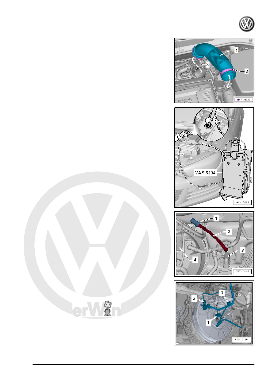
– Open the clamps -2 and 3-.
– Remove the air guide hose -1-.
– Remove the air filter housing. Refer to ⇒  Engine Mechanical,

Fuel Injection and Ignition; Rep. Gr.  24 ; Air Filter; Air Filter

Housing, Removing and Installing .

Continuation for All Vehicles
– Remove the battery holder. Refer to ⇒  Electrical Equipment;

Rep. Gr.  27 ; Battery; Battery Tray, Removing and Installing .

– Place sufficient lint-free cloths in the area of the engine and

transmission.

– Extract as much brake fluid as possible from the brake fluid

reservoir with the Brake Charger/Bleeder Unit - VAS5234- .

Vehicles with Manual Transmission
– Remove the supply hose -2- for the clutch master cylinder

-3- from the brake fluid reservoir -4-.

– Seal the supply hose -2- for the clutch master cylinder -3- using

Sealing Tool - T10249- -1- or Engine Bung Set - VAS6122- .

– Tie up the return hose -2-.

Continuation for All Vehicles
– If equipped release the connector -2- from the Vacuum Sensor

- G608- .

– Release and remove the connector -3- from the Brake Fluid

Level Warning Switch - F34- .

– Release the connector -1- from the Brake Lamp Switch - F-

and remove.

– Remove the vacuum in the brake booster by pressing the

brake pedal repeatedly.

– Remove the vacuum hose from the brake booster.

– Remove brake lines -A and B- from brake master cylinder.
– Close brake lines and open connections using Sealing Plugs

from the Repair Kit - 1H0 698 311 A- or with suitable plugs

from the Engine Bung Set - VAS6122- .

Vehicles with DSG Transmission
– Remove the selector lever cable and cable bracket from the

transmission. Refer to ⇒  Direct Shift Gearbox; Rep. Gr.  34 ;

Selector Mechanism; Overview - Selector Mechanism .

Vehicles with Manual Transmission
– Remove the connector station and cable bracket from the

transmission. Refer to ⇒  Manual Transmission; Rep. Gr.  34 ;

Selector Mechanism; Overview - Selector Mechanism .

Continuation for All Vehicles
– Remove the side cover from the driver side instrument panel.

Refer to ⇒  Body Interior; Rep. Gr.  70 ; Instrument Panel;

Instrument Panel Side Cover, Removing and Installing .

– Remove the footwell cover on the driver side. Refer to ⇒  Body

Interior; Rep. Gr.  68 ; Storage Compartments and Covers .

– Remove the driver side center console cover. Refer to ⇒  Body

Interior; Rep. Gr.  68 ; Center Console; Center Console, Re‐

moving and Installing .

– Remove the driver side storage compartment. Refer to ⇒ 

Body Interior; Rep. Gr.  68 ; Storage Compartments and Cov‐

ers .

– Remove the driver side instrument panel cover. Refer to ⇒ 

Body Interior; Rep. Gr.  68 ; Storage Compartments and Cov‐

ers; Driver Side Instrument Panel Cover, Removing and In‐

stalling .

– Remove the knee airbag. Refer to ⇒  Body Interior; Rep. Gr. 

69 ; Knee Airbags; Overview - Knee Airbag .

– Remove the footwell vent on the driver side. Refer to ⇒  Heat‐

ing, Ventilation and Air Conditioning; Rep. Gr.  87 ; Air Routing;

Overview - Air Routing and Air Distribution in Passenger Com‐

partment .

– Remove the crash bolster. Refer to ⇒  Body Interior; Rep. Gr. 

70 ; Instrument Panel Central Tube; Overview - Instrument

Panel Central Tube .

– Remove the Data Bus on Board Diagnostic Interface - J533-

and set aside. Refer to ⇒  Electrical Equipment; Rep. Gr.  97 ;

Control Modules; Data Bus On Board Diagnostic Interface -

J533- , Removing and Installing .

– Disconnect brake pedal from brake booster. Refer to

⇒ “4.2 Brake Pedal, Removing from Brake Booster”,

page 88

 .

– Remove the bolt -1- and fold the footwell trim panel -2- in the

direction of the -arrow- into the vehicle interior.

– Remove the nuts -3 and 4- from the brake booster.
– Pull the brake booster from the plenum chamber against the

seal adhesiveness.

– Carefully remove the brake booster from the vehicle.
– Remove the master brake cylinder nuts.
– Remove any heat shield.
– Carefully remove the master brake cylinder from the brake

booster.

Installing
Install in reverse order of removal. Note the following:

Note

The brake booster is only additionally glued with the seal at

the factory.

Do not replace the gluing on the brake booster and plenum

chamber, but replace the seal.

– Remove all adhesive residue from the plenum chamber and if

necessary the brake booster. To do this use Adhesive Strip

Remover - VAS6349- with a dill for example a cordless drill or

straight sander.

– Warm the adhesive residue gentle heat using a hot air gun and

remove.

– Let the Adhesive Strip Remover - VAS6349- run slowly and

rub against the direction or travel.

– Clean the surface thoroughly.
– Replace the seal -item 18- 

⇒ Item 18 (page 107)

 .

– Carefully install the brake booster and tighten the nuts.
– Attach the brake pedal to the brake booster. Refer to

⇒ “4.3 Brake Pedal, Attaching to Brake Booster”, page 89

 .

– Bleed the brake system. Refer to

⇒ “6.2 Hydraulic System, Standard Bleeding”, page 132

 .

Vehicles with Manual Transmission
– The seals -2- must be located in the return hose -1- to the

clutch master cylinder.

– Bleed the clutch mechanism. Refer to ⇒  Manual Transmis‐

sion; Rep. Gr.  30 ; Clutch Mechanism; Clutch Mechanism,

Bleeding .

Tightening Specification
♦ Refer to

⇒ “3.1 Overview - Brake Booster/Brake Master Cylinder”, page

106

♦ Refer to ⇒  Body Interior; Rep. Gr.  70 ; Instrument Panel Cen‐

tral Tube; Overview - Instrument Panel Central Tube .

♦ Refer to ⇒  Heating, Ventilation and Air Conditioning; Rep. Gr. 

87 ; Air Routing; Overview - Air Routing and Air Distribution in

Passenger Compartment .

♦ Refer to ⇒  Body Interior; Rep. Gr.  69 ; Knee Airbags; Over‐

view - Knee Airbag

♦ Refer to ⇒  Body Interior; Rep. Gr.  68 ; Storage Compartments

and Covers; Component Location Overview - Storage Com‐

partment/Covers .

♦ Refer to ⇒  Manual Transmission; Rep. Gr.  34 ; Selector

Mechanism; Overview - Selector Mechanism .

♦ Refer to ⇒  Electrical Equipment; Rep. Gr.  97 ; Control Mod‐

ules; Data Bus On Board Diagnostic Interface - J533- , Re‐

moving and Installing .

♦ Refer to ⇒  Engine Mechanical, Fuel Injection and Ignition;

Rep. Gr.  10 ; Engine Cover; Engine Cover, Removing and

Installing .

♦ Refer to ⇒  Engine Mechanical, Fuel Injection and Glow Plug;

Rep. Gr.  23 ; Air Filter; Overview - Air Filter Housing .

♦ Refer to ⇒  Engine Mechanical, Fuel Injection and Ignition;

Rep. Gr.  24 ; Air Filter; Overview - Air Filter Housing .

♦ Refer to ⇒  Electrical Equipment; Rep. Gr.  27 ; Battery; Over‐

view - Battery .

3.5

Brake Fluid Reservoir, Removing and

Installing

Special tools and workshop equipment required
♦ Sealing Tool - T10249-
♦ Brake Charger/Bleeder Unit - VAS5234-
♦ Engine Bung Set - VAS6122-


Content   ..  794  795  796  797   ..