Volkswagen Golf / Golf GTI / Golf Variant. Manual - part 586


  Index      Volkswagen     Volkswagen Golf / Golf GTI / Golf Variant - service repair manual 2013 year


Search            copyright infringement  


Content   ..  584  585  586  587   ..


Volkswagen Golf / Golf GTI / Golf Variant. Manual - part 586


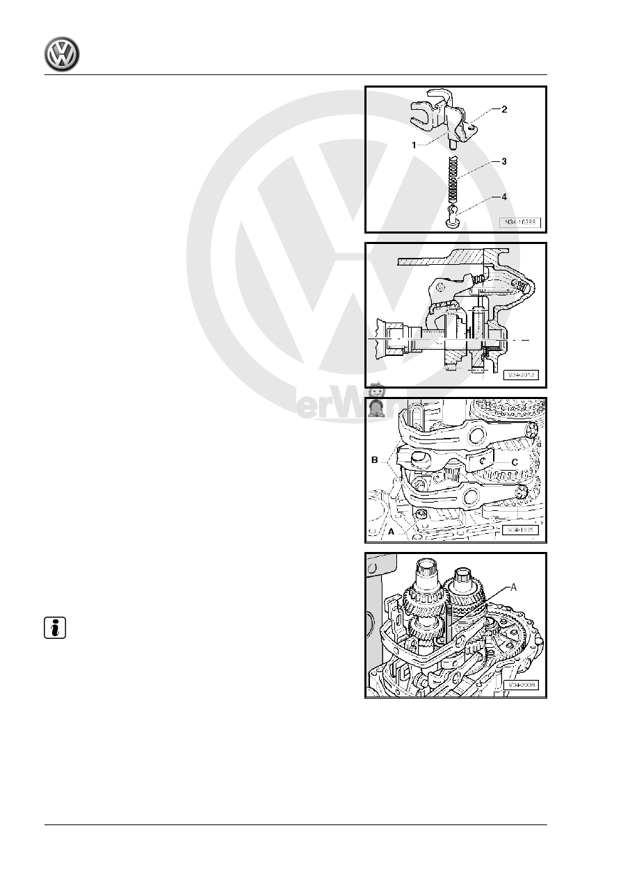
– Install the reverse gear shift fork -1- with the support for the

reverse gear shift fork -2-, the spring -3- and the sliding piece

-4-.

Reverse gear location

– Install the gearshift mechanism/reverse gear -A-.
– Install the shift forks -B- together with the gearshift rails.
Reverse gear supports -C- are located in front of selector rails.

– Install the M8 x 100 stud bolts -A- into reverse shaft support

so that this shaft is aligned after mounting the transmission

housing.

– Align the gearshift rails.

Note

The shift segments must be installed in the grooves on the locking

collars.

– Apply Sealing Paste - AMV 188 200 03- evenly onto the seal‐

ing surface of the clutch housing.

– Install the transmission housing and tighten it secure.
Install the bolts for the reverse shaft support -arrow- as follows:
– Install the bolt -a-.
– Remove stud bolts -A- (⇒ upper illustration).

– Install the bolt -c-.

Tightening sequence:
– Tighten the bolt -a- (⇒ upper illustration).
– Tighten the bolt -b-.
– Tighten the bolt -c- (⇒ upper illustration).

– Install the pivot pin -arrow- for the shift forks. To do this align

shift mechanism using a screwdriver, so that the relevant pivot

pin can be installed.

– Apply Sealing Paste - AMV 188 200 03- evenly onto the cap

sealing surface.

– Install the gearshift shaft cover.

Install the gearshift shaft cover as follows:
– Move the gearshift rail into the neutral position.
– Apply Sealing Paste - AMV 188 200 03- evenly onto the seal‐

ing surface of the gearshift cover.

– Move the gearshift shaft into neutral.
– Position the selector shaft so that selector finger -arrow- is in‐

serted into the selector rails.

– Tighten the gearshift shaft gearshift cover.

– Transmission on vehicles with Stop/Start system: install the

Transmission Neutral Position Sensor - G701- -arrow- and

tighten the screw.

– Install both flange shafts with springs, thrust washers and ta‐

pered rings. Refer to 

⇒ “2 Differential”, page 189

 .

Tightening Specifications
♦ Refer to

⇒ “5.4 Overview - Transmission Housing and Selector Mech‐

anism”, page 95

♦ Refer to

⇒ “5.6 Overview - Input Shaft, Output Shafts, Differential,

Gearshift Rods”, page 97

 .

♦ Flange shaft to transmission (conical head bolt). Refer to

⇒ “2.1 Overview - Differential”, page 189

 .

5th Gear and Transmission Housing Cover, Installing. Refer to

⇒ “5.12 Transmission Housing Cover and 5th Gear, Installing”,

page 114

 .

5.12

Transmission Housing Cover and 5th

Gear, Installing

Caution

This procedure contains mandatory replaceable parts. Refer

to component overview prior to starting procedure.

Mandatory Replacement Parts
♦ Bolts - Plate Spring to Transmission

Refer to

⇒ “5.10 Transmission Housing Cover and 5th Gear, Removing”,

page 101

 , “Transmission Housing Cover and 5th Gear, Remov‐

ing” to get a list of the special tools needed.
• Pay attention that the Bracket - Multiple Use - 30-211A- and

the Support Bridge - T10323- is installed.

– Secure the bolt on the Bracket - Multiple Use - 30-211A- with

the nut -A-.

Installed Position, 5th Gear Wheel
The groove all the way around -arrow- faces the transmission

housing.
– To install, heat the 5th gear wheel to approximately 100 °C

(212 °F) with the Inductive Heater - VAS6414- .

WARNING

Wear safety gloves.

– Install the 5th gear wheel.


Content   ..  584  585  586  587   ..