Volkswagen Golf / Golf GTI / Golf Variant. Manual - part 572


  Index      Volkswagen     Volkswagen Golf / Golf GTI / Golf Variant - service repair manual 2013 year


Search            copyright infringement  


Content   ..  570  571  572  573   ..


Volkswagen Golf / Golf GTI / Golf Variant. Manual - part 572


1.5

Selector Mechanism, Removing and In‐

stalling

Special tools and workshop equipment required
♦ Torque Wrench 1331 5-50Nm - VAG1331-

Caution

This procedure contains mandatory replaceable parts. Refer

to component overview prior to starting procedure.

Mandatory Replacement Parts
♦ Lock Washer - Cable Retainer
♦ Lock Washer - Gearshift Cable
Removing
– Disconnect the battery ground cable. Refer to ⇒  Electrical

Equipment; Rep. Gr.  27 ; Battery; Battery, Disconnecting and

Connecting .

– Remove the boot with the gearshift knob and, if necessary,

remove the noise insulation from the center console frame as

well. Refer to

⇒ “1.4 Gearshift Knob, Removing and Installing”, page 54

 .

The Footwell Rear Channel is Located Above the Bracket for the

Center Console on Some Vehicles:
– Remove the center console. Refer to ⇒  Body Interior; Rep.

Gr.  68 ; Center Console; Center Console, Removing and In‐

stalling .

– Remove rear channel footwell. Refer to ⇒  Heating, Ventilation

and Air Conditioning; Rep. Gr.  87 ; Air Routing; Overview - Air

Routing and Air Distribution in Passenger Compartment .

– Remove the nuts from the center console mounting bracket.

Refer to ⇒  Body Interior; Rep. Gr.  68 ; Center Console; Center

Console, Removing and Installing .

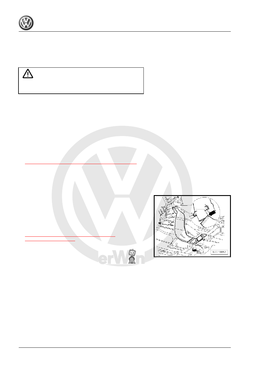
– Remove the nuts from the gearshift housing. Refer to

⇒ Fig. ““Installed Position of Gearshift Housing

Nuts -arrows-.”“ , page 57

 .

– Lower the gearshift housing.
• If it is not possible to lower the gearshift housing, then the nuts

on the gearshift housing are located under the bracket on the

center console.

• Remove the center console mounting bracket. Refer to ⇒ 

Body Interior; Rep. Gr.  68 ; Center Console; Center Console,

Removing and Installing .

If the Center Console Bracket Cannot be Removed Separately:
– Remove the center console. Refer to ⇒  Body Interior; Rep.

Gr.  68 ; Center Console; Center Console, Removing and In‐

stalling .

Installed Position of Gearshift Housing Nuts -arrows-.
– Remove the nuts -arrows-.
– Remove center console and center console mounting bracket.

Refer to ⇒  Body Interior; Rep. Gr.  68 ; Center Console; Over‐

view - Center Console .

– Remove rear channel footwell. Refer to ⇒  Heating, Ventilation

and Air Conditioning; Rep. Gr.  87 ; Air Routing; Overview - Air

Routing and Air Distribution in Passenger Compartment .

Installed Position of Noise Insulation and Gearshift Housing Nuts

-arrows-.
– Remove noise insulation and gearshift housing nuts

-arrows-.

– Remove noise insulation from the gearshift housing. Refer to

⇒  Body Interior; Rep. Gr.  68 ; Center Console; Overview -

Center Console .

– Remove the air filter housing if it is located over the gearshift

mechanism. Refer to ⇒  Engine Mechanical, Fuel Injection and

Glow Plug; Rep. Gr.  23 ; Air Filter; Overview - Air Filter Hous‐

ing or ⇒  Engine Mechanical, Fuel Injection and Ignition; Rep.

Gr.  24 ; Air Filter; Air Filter Housing, Removing and Installing .

– Remove the shift cable from the gearshift lever pins.

Disconnecting the Cable Retainer from the Selector Cable
– Pull the securing mechanism all the way forward in direction

of -arrow 1- and then unlock to the left in direction of

-arrow 2-.

– Push the relay lever forward (in direction of -arrow 3-).

Remove the Relay Lever and the Cable Retainer.
– Remove the clip -arrow 1- and then remove the relay lever

together with the cable retainer -arrow 2-.

– Remove the cable bracket from the transmission -arrows-.

Unclip the hose line -A- from the bracket -B- beforehand, if

necessary.

Caution

There is a danger of causing damage to the decoupling ele‐

ment on the exhaust pipe.

♦ Pay attention to ⇒  Rep. Gr.  26 ; Emissions Control; Over‐

view - Emissions Control .

– Remove the exhaust pipe under the gearshift mechanism. Re‐

fer to ⇒  Rep. Gr.  26 ; Exhaust Pipes/Mufflers; Overview -

Muffler .

– Remove the heat shield under the gearshift mechanism.
Removing the heat shield. Refer to ⇒  Body Exterior; Rep. Gr. 

66 ; Molding/Trim/Extensions/Trim Panels; Floor Heat Shield,

Removing and Installing .
– Pivot shift housing downward and remove with cables.

With the Relay Lever Removed: Pry the Selector Cable Retainer

Off of the Relay Lever.
– Insert a screwdriver -A- between the bushing -B- and the relay

lever.

Installing
Install in reverse order of removal. Note the following:

Installing the Selector Cable Retainer on the Relay Lever
• The relay lever is removed.
• Lubricate cable retainer locating bore.
• Grease allocation. Refer to the Parts Catalog.
• The cable retainer may only be installed at the bushing in di‐

rection of -arrow-.

• The cable retainer must move freely on the relay lever.
• The cable retainer must be behind the tab.
• Make sure it engages securely.
– Align the shift housing so that is it parallel to the body.
• The distance on both sides to the body must be equal.
Install the gearshift housing.

Cable Tie Installation Locations
– Wrap the cable tie -arrow- in a crossover pattern around the

cables and attach it as illustrated.


Content   ..  570  571  572  573   ..