Volkswagen Golf / Golf GTI / Golf Variant. Manual - part 566


  Index      Volkswagen     Volkswagen Golf / Golf GTI / Golf Variant - service repair manual 2013 year


Search            copyright infringement  


Content   ..  564  565  566  567   ..


Volkswagen Golf / Golf GTI / Golf Variant. Manual - part 566


♦ Hose Clamps - Up To 25 mm - 3094-
Removing
– Remove the entire air filter housing if the clutch mechanism

lines are not accessible. Refer to ⇒  Engine Mechanical, Fuel

Injection and Ignition; Rep. Gr.  24 ; Air Filter; Air Filter Hous‐

ing, Removing and Installing .

– Remove the battery and the battery tray. Refer to ⇒  Electrical

Equipment; Rep. Gr.  27 ; Battery; Battery Tray, Removing and

Installing .

Caution

Danger of leaking brake fluid.

♦ Be careful not to get any brake fluid on the longitudinal

member or on the transmission when performing the fol‐

lowing work. If it does, clean the area thoroughly.

♦ Place a lint-free cloth under the clutch master cylinder.

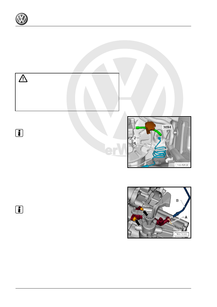
– Unclamp the supply hose -2- to the clutch master cylinder with

a Hose Clamps - Up To 25mm - 3094- .

Note

A slight deformation of the supply hose remains after the Hose

Clamps - Up To 25mm - 3094- have been unclamped.

The supply hose is therefore not defective.

After removing the Hose Clamp up to 25mm - 3094- , the sup‐

ply hose must be formed back into its original shape.

– Remove clip for hose/line assembly -1- all the way and remove

hose/line assembly.

– Seal off openings.

– Remove the clamp -A- until stop and remove the hose/line as‐

sembly -B-.

– Seal off openings.

Note

Ignore -arrows-.

– Seal the open lines and connections with clean plugs if nec‐

essary from the Engine Bung Set - VAS6122- .

– Free up the hose/line assembly and remove it.

Installing
Install in reverse order of removal. Note the following:
– Connect the hose/line assembly -1- with the connection on the

clutch master cylinder and the clutch slave cylinder.

– Pull on the line to make sure it is secure.
• After removing the Hose Clamp up to 25mm - 3094- , the return

hose -2- must be formed back into its original shape.

– Bleed the clutch mechanism. Refer to

⇒ “1.13 Clutch Mechanism, Bleeding”, page 33

 .

– Install the battery tray and the battery. Refer to ⇒  Electrical

Equipment; Rep. Gr.  27 ; Battery; Battery Tray, Removing and

Installing .

1.13

Clutch Mechanism, Bleeding

Special tools and workshop equipment required
♦ Brake Charger/Bleeder Unit - VAS5234-
♦ Bleeder Hose (670 mm) - VAG1238/B3-

Note

The system must be bled after working on the hydraulic clutch

mechanism.

Make sure no brake fluid gets on the transmission when per‐

forming the following work.

It is not necessary to pre-fill the system.

Before bleeding, fill the brake fluid reservoir to the “Max” mark‐

ing with brake fluid.

The clutch pedal is in the neutral position and is not pressed.

Brake fluid: allocation. Refer to the Parts Catalog.

– Remove the air filter housing if the bleed valve (-arrow- lower

illustration) is not accessible. Refer to ⇒  Engine Mechanical,

Fuel Injection and Ignition; Rep. Gr.  24 ; Air Filter; Air Filter

Housing, Removing and Installing .

– Return clutch pedal to the rest position.
– Remove cap from the bleed valve -arrow-.
– Connect the Brake Charger/Bleeder Unit - VAS5234- .
– Connect the bleed hose with the collector bottle pressure

hose.

If necessary use the Bleeder Hose (670 mm) - VAG1238/B3- .
– Switch the Brake Charger/Bleeder Unit - VAS5234- on.
• Working pressure 2.0 bar (29 psi).
– Open the bleed valve.
– Let approximately 100 cm (3.381 oz.)

3

 of brake fluid flow out.

– Close the bleed valve.
– Operate the clutch pedal rapidly from stop to stop, 10 to 15

times.

– Open the bleed valve.
– Let another 50 cm (1.690 oz.)

3

 of brake fluid flow out.

– Close the bleed valve.
– Turn off the Brake Charger/Bleeder Unit - VAS5234- and re‐

lease the pressure from the device completely.

– Press the clutch pedal a few times after bleeding the system.
– While doing this check the function of the clutch mechanism.
Tightening Specifications
♦ Bleed Valve. Refer to

⇒ “1.3 Overview - Clutch Hydraulics”, page 15

 .

1.14

Clutch Master and Clutch Slave Cylin‐

der, Checking

Before replacing the clutch master cylinder due to an assumed

defect, perform the 

Guided Fault Finding

 with the Vehicle Di‐

agnostic Tester first.

1.15

Clutch Position Sensor - G476- , Re‐

moving and Installing

Removing
– Move the driver seat as far back as possible.
– Disconnect the connector -arrow- from the Clutch Position

Sensor - G476- .

– Release the Clutch Position Sensor - G476- -2- on the clutch

master cylinder -1- in direction of -arrow- and remove it.

Installing
Install in reverse order of removal. Note the following:
• The tab -arrow- on the Clutch Position Sensor - G476- must

remain intact.

• The Clutch Position Sensor - G476- must engage audibly.
• Adapt the Clutch Position Sensor - G476- in the 

Guided

Fault Finding

 using the Vehicle Diagnostic Tester .

1.16

Clutch Release Mechanism, Servicing

Special tools and workshop equipment required
♦ Torque Wrench 1331 5-50Nm - VAG1331-
• The transmission is removed.
Remove and Install the Clutch Release Lever with the Release

Bearing
– Disengage the spring -arrow 1-.
– Remove the clutch release lever -arrow 2- and release bear‐

ing.

– Install in reverse order of removal.

Removing and Installing the Release Bearing
– Squeeze the hooks -arrows- on the back of the clutch release

lever and remove the release bearing -A- from the clutch re‐

lease lever.

– Press the release bearing -A- into the clutch release lever until

the hooks -arrows- engage.

– Install the transmission. Refer to

⇒ “2 Transmission, Removing and Installing”, page 67

 .


Content   ..  564  565  566  567   ..